


THE PREVENTION OF FIRE ON VEHICLES.
Page 76
If you've noticed an error in this article please click here to report it so we can fix it.
A Rdsumd of Recently Published Patent Specifications.
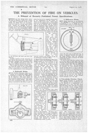
MEERE 'are few things more calm:listed to disturb a party on a coach or bus than .an outbreak of lire on the whicie on which they are travelling, even if it May be of the most trivial .Patent No. 278,354, by H. C. Beam, of New South Wales, describes a' holder for a fire extinguisher which, when the extinguisher is removed from its place, causes the supply Of petrol to ie cut off Autovac. from the tank and from the Another feature of the invention is that should the carburetter catch alight through a backfire, the extinguisher can ho used without removing it from its place•and without opening the bonnet. This is done by-means of pities which run from: the nozzle: of the, extinguisher while it is in place in its holder to jets in the neighbourhood of the carburetter, A Hydraulic Brake. • FROM _British Columbia comes an in
vention of a hydraulic brake, Which is described in patent No. 284,768' by W. B. Charters., The main object Of the invention appears: to be to do away with wear of .brake linings.The, brake is' of the transmission .type and is not always c•onnected to the drive, a pair of gears having to be engaged preparatory to the application' of 'the brake, as shown in the upper view. When theSe gears are in engageinent, the wormshaft effect is produced until, a further operapistons, as shown in the lower view. These pistons are both fitted with valves, ries an eccentric which oPerates, two tion is performed. Tim shaft (A) car(A) is set in motion, but no braking as shown on the left in the sectional view, By this means, as. each piston moves away from the shaft . it forces o.i1 iu " the direction indicated. by arrows. A throt:tie is placed where the two streams meet and is fitted with clock valves which allow oil, to return to the central chamber so long us the throttle be open. . A• partial closing of the throttle restricts the passage of the oil,
so producing a braking effect. • A New Case-hardening Process. THE subject of case-hazdening is one
that is 'always of interest to the motor inchlstry. .None of the processes. now in general use given entire satisfaction, for 'warping and other troubles are still with Us and .perhaps will be 'so long aS the heating of the articles to be hardened forms part of the. process. Any improvements. in the process are therefore welcomed. Patent No. 277,039, by the Deutsche . Cold-und-Silber-Scheideanstair, of Frankfurt, . describes what isclaimed to he an improvement in what is known as the cyanide process. By adding finely divided carbon to the-bath of cyanide, the frothing effect at high temperatures is, avoided. BY thiS means, it is Claimed. higher temperatures reay be employed in the . bath,, of molten cyanide, by means of which a glass-hard surface. Comm be 'obtained. Owing .to.. the warping that takes place in such article's as 'crankshafts, is usually neces-iary •
to • regrind •.• the
article after harden.
log to ensure even it moderate degree of truth.. B e f r e grinding it is usually' necessary' to straighten the article under a press to bring it to an 'approximately true form so that the comparatively thin
skin of hardened metal is not removed in the grinding. We have, however, recently seen a large crankshaft which had been case-hardened after it had been finished. It was absolutely • true in every detail, had not been reground,and showed no marks of
straightening under a press. A Half-servo Brake.
THE brake described in specification No. 21)3,260, P. A. Scott_Inverstin, of. Copenhagen, is ono in which one shoe • acts in a self-assisting or servo manner, whilst the other shoe is self-relieving. A wedge is imposed between the ends of the shoes farthest from the fulcrum, which has the effect of forcing the shoes against the drum.
It will be seen that the wedge is not of an even agle on both sides, the side affecting the self-assisting shoe being of a greater angle than the one affecting the. self-relieving shoe. By this means, we 'presume,an. even pressure is obtained on both shoes so long as the direction of rotation is as indicated by the arrow.. It would appear that this brake is intended aS a one-way brake. A cam ia erriploYod to actuate the wedge, but it is not easy to 'see how this could be carried out as shown, as the plunger
would normally foul the axle. .
A Two-stroke Friction Clinch. THE clutch described in specification. No. 288,484, of H. ft. Dickinson and 1.1. K Basset, is a combination of a single-plate and a cone, the idea being that the single plate will take up gently and so get the vehicle moving, whilst the cone, when it engages, will transmit the final drive. In the figure on the left, the plate and the cone are both disen gaged. The central figure shows the plate only in engagement, whilst the right-hand figure shows the cone and the plate engaging. The plate is mounted so that it can recede to allow the cone to engage when rotary movement has once beeii imported to the sliding 'member.