


THE FIRST FORWARD-DRIVE SIX-WHEELER.
Page 62
Page 63
Page 64
If you've noticed an error in this article please click here to report it so we can fix it.
A Special Guy Chassis, Built to Suit the Requirements of the India Office,and Giving a Large Platform Space.
WE who live in England where, comparatively speaking, excellent roads abound, seldom appreciate the difficulties which must confront the operators of mechanically propelled vehicles in overseas countries. Roads there, as we understand the term, do not exist at all, except in the towns and cities. The main trunk connections between the towns, often hundreds of miles apart, are merely tracks with no proper foundation and quite unmetalled. These
conditions, of course, call for a special type of vehicle, .much more• robust in construction than is found necessary for normal work in England. On the other hand, however, development work, even in our own country, requires special appliances, so there would seem to be a great number of lessons to be learnt from the• vehicles built 'to suit overseas conditions.
We recently had the opportunity of inspecting a new Guy lorry chassis, built to the requirements of the India Office, and as something of a departure from everyday practice was apparent, it was thought that it would prove of interest to readers of The Commercial Motor.
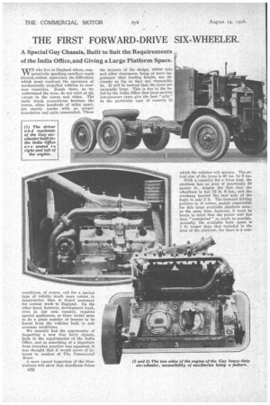
A mere casual inspection of the illustrations will show that sturdiness forms B36 the keynote of the design, whilst axle and other clearances, being of more importance than loading height, are obviously as big as they can reasonably be. It will be noticed that the tyres are unusually large. This is due to the belief by'the India Office that large-section low-pressure tyres give the best " grip " in the particular type of country in which the vehicles will operate. The actual size of the tyres is 40 ins. by 9 ins.
With a capacity for a 3-ton load, the platform has an area of practically 88 square ft., despite the fact that the wheelbase is but 12 ft. 6 ins., and the overhang beyond the rear axle of the bogie is only 3 ft. The forward driving position is, of course, mainly responsible for this large available platform area ; at the same time, however, it must be borne in mind that the power unit has been " compacted " as much as possible. Actually, the available body space is 1 ft. longer than that included in the area of the platform, for there is a corn partraent behind the dash to carry two spare wheels. This position for the spares is not shown in the photographs, because the compartment is included in the body. In passing, it might be mentioned that there is a special winch gear fitted to the vehicle to enable one man to change a wheel--a very desirable feature in a vehicle intended for overseas use.
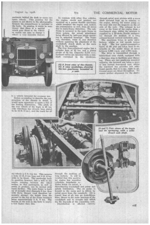
Before proceeding to describe the construction of the chassis in detail, it would seem opportune to quote a few of the leading dimensions. The pitch of the rear wheels of the bogie is 45 ins. (the wheelbase has already been stated to be 12 ft. 6 ins.), and the track for all six wheels is 5 ft. SA ins. This permits a body 13 ft. ..6 ins. long and 6 ft. 6 ins. wide to be fitted. The particular body in question, however, has a well in the centre running between the wheel arches, so that passengers, as well as goods or produce, can be carried with equal facility. The main frame is built up of straight steel channels 5 ins, deep with 21-in. flanges (and therefore immensely strong), the height from the ground to the top of the frame members being approximately 2 ft. 9 ins. The bottom of the well in the body is nearly a foot higher than this. In common with other Guy vehicles, the engine, clutch and gearbox are mounted on a patent flexible sub-frame which insulates the engine and, indeed, the transmission as well, from all stress due to main-frame distortion. The subframe is mounted in the main frame at three points, the actual attachment being effected by ball-type joints operating in spherical housings. The frame can, therefore, twist in any direction without upsetting the alignment of the crankshaft, clutch shaft, or the main shaft in the gearbox.
The Guy four-cylindered engine has a cylinder bore of 4f ins, and a piston stroke of 51 Ins. (capacity 5,114 c.c.). Inclined valves are operated from a camshaft contained in the crankcase, through the medium of long rockers. It will be recalled that this particular engine has monobloc cylinders, detachable cylinder heads (in Pairs), a three-bearing crankshaft and pump and splash lubrication. The oil pump is housed in the sump and is driven by spiral gears from the camshaft. Oil is forced, first of all, into an Auto-Klean filter, thence to the main bearings of the crankshaft and to troughs into which dip the big-ends of the connecting rods. Distribution is effected entirely
through spiral spur pinions with a cross shaft situated high up in relation to the engine, driving the water pump ozt the near side and the magneto on the off side of the unit. The exhaust is led away at the front of the engine from a four-branch pipe, whilst the mixture is supplied by a 25-choke Zenith carburetter through the medium of a long exhaust-heated vertical induction pipe.
The maximum b.h.p. is quite satisfactory, whilst at low speeds torque is high. The low petrol-consumption figure of .68 pint per b.h.p. hour is obtainable at the useful range of speed between 1,200 r.p.m. and 1,700 r.p.m.
The drive is transmitted through a fabric-lined cone clutch, equipped with disc-type stop to facilitate gear changing. There are two gearboxes mounted unitwise, the forward one being a more or less normal four-speed type, whilst the rearward one provides two additional speeds, that is to say, eight in all. Ground gears are fitted throughout. To ensure perfect alignment for the shafts of both boxes, • a single-bearing honsing is used for the shafts in each box and is spigotted into both end covers. There is a power take-off on the near side of the forward box where a tyre pump is fitted.
The control of the gears is placed at the left hand of the driver, one lever operating the changes in the four-speed and the other those in the two-speed box. The four-speed control operates a sliding and rocking shaft fitted with balland-socket joints throughout and mounted in spherical bearings, the seatings for which are carried on the sub• frame. A lever for the auxiliary box operates in much the same manner as a normal ball-jointed steering gear drag
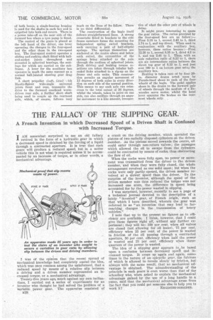
A short propeller s'Aaft, Lttetl .-ith Hardy-Spicer wide-angle universal joints front and rear, transmits the drive to the forward overhead wormdriven rear axle, a further short shaft being used to couple up the rearmost axle, • which, of course, follows very
much on the lines of its fellow. There is no third differential.
The construction of the bogie itself follows straightforward lines. A strong eross-tube fitted in brackets to the side frame members forms the mounting for independent spring swivel brackets, each carrying a pair of half-elliptic springs. The springs themselves are anchored at the centre above and below each swivel, the extremities of the springs being attached to the axle through the medium of spherical joints. Both driving and braking torque reactions are taken through tubular ball' ended links attached to a rig-up on the frame and axle units. This construction permits an angular movement of 13 degrees of both axles in every direction on each side of the normal position. This means to say each axle can crisscross to the total extent of 26 degrees, whilst the wheels, taken in pairs on one side, can also oscillate through an angular movement to a like amount, irrespec tive of what the other pair of wheels is doing.
It might prove interesting to quote the gear ratios. The ratios provided by the four-speed box are as follow :— First 5.18 to 1, second 3.46 to 1, third 1.74 to 1, and top direct. When used in conjunction with the auxiliary box, however, these ratios become :—First 12.38 to 1, second 8.35 to 1, third 4.2 to 1, and top 2.41 to 1. Thus, with an axle reduction ratio of 8.33 to 1, there are six intermediate ratios between the direct top gear of 8.33 to 1, and just over 100 to 1 on bottom gear using the auxiliary box.
Braking is taken care of by four 20in. diameter drums acted upon by Ferodo-lined shoes to each of the four wheels of the bogie. The pedal applies shoes-in the drums to the forward pair of wheels through the medium of a Dewandre servo motor, whilst the hand lever operates the brakes on the rearmost wheels only.