


EVERY INCH OF BUS LE]
Page 58
Page 59
Page 60
Page 61
If you've noticed an error in this article please click here to report it so we can fix it.
El A REVENUE EARNER.
A New Departure in Bus Design which Provides Seats for 40 and Standing Re mates the Conventional Chassis and r '60 Passengers on a 30-ft. Vehicle.
T"present method adopted in large eitlis, to deal with such passenger traffic as would be expected to travel upon public conveyances—tramcars and motorbuses—is not necessarily ideal, as is, in fact, proved by the developments which in recent years have taken place in motorbus design. The tramcar, in the main, has stood still in the matter of design for the past 20 years, for since the introduction of electric
traction there has not really been scope for very much alteration in the tramcar. It still carries from 65 to 80 passengers in double-deckers according to its sire, and it has only been within the past 12 months that the London County Council—to take an example—has been able to effect a small improvement in placing some of the seats in the lower saloon transversely instead of the whole of them being arranged longitudinally.
Our Own Marvellous Bus Developments.
The motorbus has, since the war, developed from the 34-seater B-type, as was used in London, and the still smaller vehicle in occasional use in the provinces, to the 72-seater six-wheeled vehicle, passing through the various stages, which each gave a higher seating capacity, to the double-deck bus with a roof to the upper saloon, all seats being upholstered and the rear staircase being enclosed, Again to take London as our example, the 72-seater bus is agreed to be unnecessary on the majority of routes. It can only be employed economically where there is a high volume of traffic throughout the day's working. The bus which is the most economical is that which seats between 50 and 56 passengers. Its running costs and overhead charges are not high for the average loading per journey, but its chief defect is that it does not provide room for more than five persons to stand comfortably under conditions of peak-hour loading.
There is a line of thought not only in America (where expression has already been given to it), but also in this country, that there is scope for the development of a different type of vehicle that shall provide seating accommodation for the average journey loading during the ordinary hours of the day and shall be able to accommodate a large number of standing passengers—or "standees," as they are called in America—during the hours of peak load. In some cities of the United States an overload of as much as 150 per cent, is considered not unreasonable, so that a vehicle which will normally seat 40 passengers will take as many as 100 when it is packed to repletion.
It is such a vehicle that we propose now to describe, the first of the series having been made.by the American Car and Foundry Motors Co., of New York City, associated with which is the .1. G. Brill Co., of Aldwych House, Aldwych, London, W.C.2.
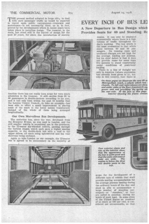
This vehicle is really unique in every respect, for it distinctly breaks away from the conventional motor vehicle construction which comprises a self-contained chassis superimposed upon which is a wooden body to accommodate passengers. Such a vehicle as the latter has never really been ideal, because the chassis frame, which is a beam between two axles, has never had sufficient rigidity to prevent relative movement between itself and the body ; the chassis has been able to yield and to twist, creating a need for three-point suspension of the power unit and for universal joints in the transmission line, and even when frames as deep as 10 ins. or 11 ins, have been employed, adequately braced and stiffened to the limit of the ability of the designer, there has been racking and weaving of the superimposed body, involving, eventually, the destruction thereof and, incidentally, imposing upon designers and builders the need to make the bodies inordinately heavy and stiff in order to resist the twisting effect of the non-rigid chassis frame.
Thk matter for wonder is that the chassis and the body of the average British-built passenger vehicle invariably do stand up to the work and give quite a fair period of service.
In the case of the Metropolitan coach chassis made by the American Car and Foundry Co., there is no chassis frame at all. The structure consists of an allsteel body, suitably cross-membered and so constructed that it is calculated to be free from the weaving, loosening and disintegration influences referred to.
The engine Is supported in the floor framework and the two axles are attached to springs which are shackled to suitable members of the body framework. The net effect of this is to produce a vehicle which, calculated upon the basis of a full passenger load, weighs about 100 lb. per passenger seat less than the conventional motorbus.
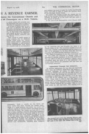
Appearance Unusual but Attractive.
In exterior appearance the bus does not materially differ from the ordinary single-deck bus employed in America, although, of course, It looks somewhat unusual to British eyes, and we are able to give two exterior views, one showing the entrance. side (which, according to American road customs, is on the righthand side of the vehicle) and a three-quarter front view. From these it will be seen that there is no bonnet and, as a matter of fact, the disposition of the power unit is rather unusual in that it is placed practically midway between the two axles. This is a point with which we will deal later. The loading level is moderately low, the height from. the ground to the step being 14 ins., and from the step to tlw deck or platform, 12 ins. There is a mininunn head-room of 6 ft. 5 ins, under the roof cross-mcinbers, so that' the overall height of the vehicle is abet'', 9 ft. 4 ins.
As we have said, the carrying i_apacity is 40 seated passengers; yet this capacity is obtained upc..t an overall length of but 30 ft., which, however, does not include the bumper bars at the ends. The wheelbase is 19 ft. 2 Ins, and the track at the front it 6 ft. 8 ins, and at the rear 6 ft. 2 ins. The minimum road clearance given throughout is S ins., whilst the vehicle Will turn in a radius, either to the left or right, of 38 ft. It will thus be seen from these dimensions that the vehicle is compact for its seating capacity but its turning circle is 16 ft. larger than that of the London NS bus.
The Original Method of Construction.
To deal now with the form of construction, which we may say is the outcome of yeats' of study not only of operating problems but of structural design by the experts employed by the A.C.F. These operating problems include the -question of maintenance and equipment, for it is • the contention of the designers that the vehicle expressly scores on the question of cheapness of maintenance. As the body cannot be racked to pieces, there is here one important saving in cost. The power plant is readily removable as a unit and the axles may be removed by jacking up the coach and rolling the axles out. 15 fleet operation, a small stock of spares permits the replacement of any component that requires nttention or overhaul, thus enabling the vehicle virtually to be able to give about a 95 per cent. service.
The basis of the construction of the vehicle is a continuouS sill of 21 ins. by 2 ins. by TV in; steel angle. lt. goes almost completely round thebody; being bent to form the outer edge of the wheel housing, and at the
front being replaced by a 7-inch structural steel channel which is regarded as a non-telescoping anti-collision framing. There are additional reinforcing angles under the door openings.
Sixteen inches above the sill is another steel angle . and there is a continuous steel belt rail all round just below the window. openings. Steel 'plates riveted to the sill and rails and to the pillars form a plate girder
n34 44 inches deep and extending all round the body except at the door openings, the wheel housings and the radiator gap. The wheel housings are of sheet steel.
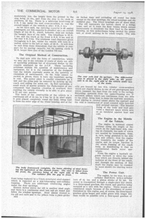
The sill represents the bottom chord of a bridge truss, and on it rests the floor beams which extend transversely to distribute the floor load to the under framing, on this under-frame being carried the power unit at about midway in its whole+ length. The side sills are braced by two 6-in, tubular cross-members which are clearly shown in one of our photographs and which transmit the load from the body to the springs. Extending upwards from the under-framing are Tsectioned pillars which are continuous from one side to the other, being bent to form the roof-side members. Steel plating is carried round above the cantrail and the roof is constructed of wood covered with hair-felt and painted canvas. The interior lining of the body and 'roof pro ides a dead-air space which acts as an insulator against heat and cold.
The Engine in the Middle of the Vehicle.
The engine is mounted almost midway along the length of the coach on the right-hand side, resting on channels, the ends of which are carried by cross-beams, these, in turn, being gusseted to the side sills and pillars; thus the engine bed transmits the weight Of the engine and its torque reaction to the whole framing of the coach body, so distributing it that no concentrated loads occur. any where.
From the engine a layshaft extends forward to drive the twin fans which are directly behind the radiator at the front of the coach, and through the medium of this shaft the engine may be cranked by band should the starting motor fail. .
The Power Unit.
The engine, by the way, is a sixcylhider Ilall-Scott with a cylinder bore of 44 ins, and a piston stroke of 51 ins. Its power is transmitted through a single-plate -dry clutch to a three-speed gearbox, the clutch and gearbox being' mounted as a unit with the engine. Three speeds are considered ample because of the abundance of power furnished by this engine, and, of course, the three-speed gearbox -gives larger and wider gears with longer life than would be possible with a four-speed gearbox of
the same size, and there is faster acceleration when on first or second gear.
The driving shaft is short and straight and has two Spicer universal joints. It does not set up drive-shaft vibration, because its angularity is small, and it is free from whip because it is short. The final drive is taken through worm gearing, the axle being truly full floating.
On the tubular cross members of the coach body are attached spring banger brackets, and the weight of the coach is carried on a one-piece cast-steel axle housing, the spring seats of which are cast integrally with it. It is 5 ins, in diameter at the spring seat and hence has an unusually generous factor of safety.
The axle shafts are freely splined at both the inner and outer ends, and in order that the wheels may be able to do as they always want to do, to wobble slightly as they turn, the axle-shaft and hub-plate are not rigidly attached, and thus the axleshafts are relieved of all but torsional driving stress and are subject to no bending strain whatever.
The differential pot of the axle casing is located on the right in line with the shaft of the power plant. Both the worm and wormwheel are oversize, the worm being supported by two large Timken roller bearings, whilst at the front end it floats in a Hyatt roller bearing, being free to expand without bending as it attains normal operating temperature. The worm and the wheel are retained as a unit in a carrier and may be• adjusted on the bench away from the coach.
The front axle is I-beam in section, of drop-forged, heat-treated steel with highangle Timken roller bearings on tile steering knuckles in order to make the steering easy.
The steering gear, which is of the screw-and-nut type, is mounted almost directly over the front axle with the drag link disposed trans versely instead of fore and aft; thus, spring deflection does not affect the steering.
The Air-operated Brakes.
The service brakes are operated by air in the four wheels, the shoes being of cast-alloy steel and the drums being exceedingly hard. The rear-wheel brakes are 161 ins. by 6 ins, and the front-wheel brakes ins. by 4 ins., so that the total service brake area is 1,036 sq. ins., nearly 1 sq. in. for every 20 lb. of the normal loaded coach. Being air-operated by a slight pressure on a pedal, the brakes impose no physical labour on the driver, and there is a supplementary brake operated by. a lever acting on a 16-in. drum on the transmission shaft.
The front springs are semi-ellipties:49 ins, long and 4 ins, wide with long, thin leaves which give easy riding. They are mounted by pins in brackets riveted to the anti-collision front member and are shackled at their rear to the front floor-beam channel, and they may therefore be easily detached from the coach body and a complete new axle assembly, with its springs mounted, rolled into 'place. The rear springs are 64 ins, long by 5 ins, wide and are devised to act in
three stages. On top of the main spring is a helper spring, the opposite ends of which make contact successively with brackets on the under-frame of the coach as the load is increased. When the vehicle Is empty, the main spring carries the load; with a normal passenger load, one end of the helper spring makes contact with the under-frame bracket, whilst when the vehicle has its full overload, both ends of the helper spring assist in carrying the load.
The tyres are six 38-in. by 9-in, pneumatics, each having a capacity of 5,000 lb. The twin rear tyres are calculated to have a weight distribution to take 70 per cent, of the full overload weight, and the front tyres 30 per cent. of it, With a 100-passenger loading the rear tyres are thus slightly overloaded, but with 80 passengers the tyre lead is rather less than that for which the tyres are rated.
The coach is said to be extremely easy to handle.
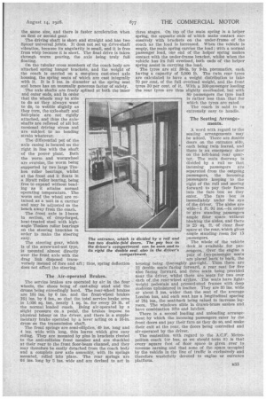
The Seating Arrangements.
A word with regard to the seating arrangements may be added. There are double doors on the entrance side, each being twin leaved, and there is an emergency door on the left-hand rear quayter. The main doorway is divided by a rail sothat incoming passengers are ' separated from the outgoing passengers, the incoming passengers keeping to the right of the rail and moving forward to pay their fares into the fare box as they enter. The fare box is immediately under the eye of the driver. The aisles are widel ft. 9gins—in order to give standing passengers ample ildor space without blocking the aisles, and there is 25 sq. ft. of clear floor space at the rear, which gives ample standing room for 15 passengers.
The whole of the vehicle deck is available for passengers. Over the engine a pair of •two-passenger seats are placed back to hack, the housing being thoroughly gas-tight. Then there are 12 double seats facing forward, a rear seat for thre also facing forward, and three Seats being provided near the driver, whilst there are seats for two over each of the rear-wheel arches. The seats have lightweight pedestals and pressed-steel frames with deep cushions upholstered In leather. They are 35 ins, wide or about 3 ins. wider than the seat of the average London bus, and each seat has a longitudinal spacing of 28; ins., the seat-back being raised to increase legroom. The windows slide in drawn-brass sashes and have combination lifts and latches.
There is a second loading and unloading arrangement by which the incoming passengers enter by the front doors and pay their fare as they do so, and make their exit at the rear, the doors being controlled and air-operated by the driver.
The contention with regard to the A.O.F. Metropolitan coach (or bus, as we should term it) is that every square foot of floor space is given over to revenue earning and that none of the space occupied by the vehicle in the line of traffic is exclusively and therefore Wastefully devoted to engine or entrance platform.