


Patents Completed.
Page 24
If you've noticed an error in this article please click here to report it so we can fix it.
Complete specifications of the following patents will be sent to any address in the United Kingdom by the Sales Branch, Patent Office, Holborn, W.C., upon receipt of eightpence per copy.
A Heavy Oil System.
L. Smith, and E. Page, No. 16,964, dated the 20th July, 1912.—According to
this invention means are provided for using an oil heavier than petrol, such as paraffin, in an ordinary carburetter for use in an internal-combustion engine. A small chamber is attached to the cylinder so as to be heated by conduction. This chamber can conveniently take the place of the plug usually placed over the exhaust valve. The oil is fed to the lower portion of the chamber so as to come first into contact with the highlyheated walls of the chamber and then flows to the carburetter where it mixes with air. The oil can be made to flow thiough a series of these chambers in order to be thoroughly heated. For the pm-pose of starting up when cold, a bypass on the pipe from the oil supply of the carburetter is provided with an electric heater which may consist of a wire coiled around the by-pass.
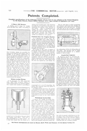
Water-cooled Piston.
0. E. Jorgensen, No. 7471, dated 3rd July, 1913.—This invention relates to water-cooled pistons for internal-combustion engines and consists in providing a central core to the piston through which the cooling water flows. This core is also surrounded by a water jacket. As it has been found that the centre of a piston is its weakest part, this invention provides for strengthening that part and supplying the cooling water directly to the centre. This is accomplished by taking the hollow piston rod right through the piston and placing the water supply pipe through this hollow rod. The rod is provided with a flange by which it is bolted to the piston.
Control Gear for Engine Starter.
J. I. Thornycroft and Co., Ltd., No. 14,474, dated 20th June, 1912.—This invention relates to a starting and controlling gear for use with that class of multicylinder internal-combustion engine employing compressed air for starting, in which the compressed air starting valves and fuel admission valves are selectively brought into operation.
It is usual in this class of engine to divide the engine cylinders into sets, and to employ a separate eccentric bearingshaft fur the valve levers of each set, by which moans the engine can be started with compressed air supplied to all the cylinders. One set will run explosively, whilst compressed air continues to be supplied to the other set, after which both the sets run explosively and finally the compressed air is cut off altogether, the engine then running under the action of its ordinary cycle. According to this invention, the several movements of the valve control shaft are brought about by a single complete revolution of a control spindle fitted with a hand wheel by means of link mechanism connected to arms on the valve control shaft.
Petroleum Carburetter.
P. Baxter, No. 16,030, dated 9th July, 1912.—This invention relates to carburetters for use with oils requiring to be vaporized before use in an internal-combustion engine. It consists of a cylindrical mntal chamber having inlet and outlet orifices for the passage of exhaust gases, and arranged within this chamber is a smaller cylindrical fuel chamber which is provided with an inclined end wall upon which the . exhaust gases dirntly impinge. This fuel chamber is packed with a suitable heat-retaining material. such as coiled metal wire. The fuel int.A. nozzle is arranged so that the oil, upon entering the fuel chamber, impinges directly upon the heated inclined end of this chamber and there broken up.
The air inlet pipe is coiled around the fuel chamber and enters this chamber at the opposite end to the fuel inlet. In line with the end of the air pipe is located the bell-mouthed end of the mixture pipe, the carburation of the air taking place at this point. The mixtui:e pipe is coiled around the fuel chamber in a similar manner to the air pipe.
Liquid-fuel Injector.
W. Cameron and H. G. Burford, No. 10,499, dated 3rd May, 1912.—According to this invention, part of the air which is admitted to the working cylinder of internal-combustion engines using liquid fuel, is passed to a small cylinder and highly compressed; it then serves to inject the fuel into the working cylinder, where it mixes with the main air charge and is ignited by the usual spark. This is accomplished by providing the working cylinder with a by-pass communicating with a small cylinder which is termed the super-compression cylinder. At the top of this cylinder is arranged a valve which is opened when the piston reaches the end of its upward stroke. It will therefore be seen that upon the compression ftroke of the piston part of the air which has been admitted to the cylinder is forced through the passage into the super-compression cylinder. The air is here very highly compressed and when the piston reaches the end of its stroke the valve is opened. admitting air to the oil-supply valve ; the pressure of this air, overcoming that of the oil-valve control spring, injects the fuel in an atomized condition into the working cylinder.