Limited-action Differential
Page 82

If you've noticed an error in this article please click here to report it so we can fix it.
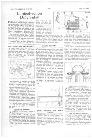
PATENT No. 860,546 refers to fourwheel-drive vehicles having a differential between each wheel and one between the two propeller-shafts. With such an arrangement, slip of one wheel can lose the entire drive and the subject of the patent is a means of preventing this. (Harry Ferguson Research, Ltd., "Abbotswood," Stow-on-the-Wold, Glos.)
The drawing shows the complete transmission which starts with a torqueconverter (1), followed by an epicyclic reduction gear (2), and then a two-speed and reverse gearbox (3).
An output shaft (4) from the gearbox drives the planet-carrier (5) of the DISC BRAKE PAD REPLACEMENT
1-1 A DISC brake forms the subject of
patent No. 861,091. The chief feature is that when worn the friction pads can be easily and quickly replaced with the minimum of dismantling. (Dunlop Rubber Co., Ltd., I Albany Street, London, N.W.1.) The drawing is an exploded view of the construction. The disc (1) passes through a caliper structure (2) to the outer faces of which are bolted the hydraulic cylinders (3 and 4).
Square section friction pads (5) can be inserted by simply sliding them in radially. They are recessed at 6 to locate them on the hydraulic pistons (7).
The pads are retained in position by a channel member (8) which is secured to the caliper by a single bolt. Inward movement of the pads is prevented by clips (9) mounted between the caliper and hydraulic cylinders.
A second patent numbered 861,092 also deals with the brake and references are made to an earlier one numbered 688,382.
SIDEWAYS PARKING
ASCHEME for enabling a vehicle to move itself sideways is the subject of patent No. 861.998. The aim is to facilitate parking. A powered roller under the rear axle can be lowered to the ground; this lifts the rear wheels clear and stews the tail end of the vehicle into the kerb. The patent comes from Fiat Societa per Azioni, 200 Corso Giovanni Ahnelli, Turin, Italy.
c42 differential w hich divides the drive between the front propeller-shaft (6) and the rear one (7).
The essence of the invention is the use of a pair of one way clutches of freewheels (8 and 9). The inner members are both attached to the rear propeller-shaft and if the difference in speeds between the outer and inner members exceeds certain figures due to slip at the front or rear wheels, a positive drive is imparted to the rear shaft.
ENGINE HEATING
ADEVICE for warming the water in the cooling system of an engine and at the same time the oil in the sump forms the subject of patent No. 861,419. The scheme overcomes the objection to direct-immersion heating for increasing oil temperature in that this can cause local overheating and decomposition of oil. (E. Lewcock, 717 Hanworth Road, Hounslow, Middlesex.)
In the drawing (1) is a tube containing the electric heating element and (2) the terminals for connection. The tube •is surrounded by a copper cylinder (3) which bolts on to the side of the sump via a flange (4).
The copper cylinder forms a water jacket, being connected to the main cooling system by flow and return pipes. This means that at no time could the temperature of the cylinder in contact with the oil rise above the boiling point of water. A thermostat (5) may be included to speed up the temperature rise.
EXTRA RIGIDITY FOR WORMWHEELS
WORM drives in a rear gear axle have the merit of quiet running and. provided adjustment and lubrication are correct, give reasonable efficiency. A .scheme for minimizing errors in meshing forms the subject of a patent No. 861,585. (Leyland Motors, Ltd., Leyland, Lanes.)
The drawing is a section through the worm drive of a rear axle. The worm is shown at (1) and the wormwheel at (2). When under load, the side-thrust of the worm tends to push the wormwheel to one side. To prevent this, the present scheme proposes to provide rigid support members.
rhese consist of adjustable thrust-screws (3), two on each side of the wormwheel. The screws have rounded heads, and carry rubbing caps (4) which make contact with, the wheel and are slightly chamfered on their rubbing surfaces to trap oil. The caps are adjusted so as to give running clearance when the gears are not loaded, coming into operation only when side-thrust is encountered.
AUTOMATIC OIL-LEVEL
A DEVICE for indicating the level of the oil _in an engine is the subject of patent No. 858,753 from 0. Metzler. 108 Ludwigstrasse, Offenbach/Main, Germany. A float resting on the oil is arranged to make an electric contact and so warn the driver when the oil is low.
AUTOMATIC LIGHTING-UP
AN automatic light switch for use on parked vehicles forms the subject of patent No. 861,441. It consists of e clockwork mechanism that can be pre-sei to close the lighting 'circuit at t suitable time. The patent comes froh A. Burnett and J. Showell, Luxor Villa Princes Street, Cheltenham.
NEW IGNITION SCHEME
PNos. 861,689 and 861,69( both come from General Motor Corp., Detroit, Michigan, U.S.A. The deal with an ignition system in which thi condenser and coil primary are in circuit coupled to a relaxation oscillator Transistors form part of the scheme.


