


A Simple Pilot Injector
Page 60
If you've noticed an error in this article please click here to report it so we can fix it.
PA.1 ENT No. 634,024 comes from C.A.V., Ltd., and W. Nicol's, both
of Warple Way, 'London, and discloses a design for a pilot injector, that is. one giving two distinct spurts of fuel at low and-high Pressures respectively, In the scheme shown, there is a momentary closure of the .needle-valve
between the two phases .of .injection. .
Referring to the .drawing, the fuel . arrives via port I and when a moderate pressure has been built up-the valve (2) is opened in the usual .way, against a spring (3). As the pressure continues to rise, it can, via a cross-port (4), reach an internal valve (5), which, although having a greater closing force, is eventually opened. It remains open until its head (6) reaches an abutment (7), after which the reaction forces re-close the outer valve and momentarily interrupt the injection. When full pressure is reached, the valve (2) is reopened in the original manner.
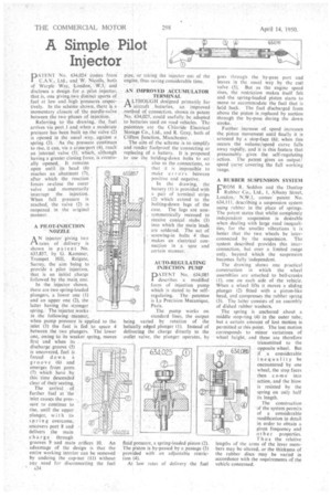
A PILOT-INJECTION NOZZLE
ANinjector giving two rates of delivery is shown in pa tent No. 633,857, by G. Kammer, Trumpet Hill, Reigate, Surrey. the aim being to provide a pilot injection, that is an initial charge followed by the main one.
In the injector shown, there are two spring-loaded plungers, a lower one (1) and an upper one (2), the latter having the stronger spring. The injector works in the following manner; when pump pressure is applied to the inlet (3) the fuel is fed to space 4 between the two plungers. The lower one, owing to its weaker spring, moves first and when its discharge groove (5) is uncovered, fuel is forced d own a groove (6) and emerges from ports (7) which have by this time descended clear of their seating.
The arrival • of further fuel at the inlet causes the pressure to continue to rise, until the upper plunger, with its spring overcome, uncovers port 8 and delivers the main charge through grooves 9 and main orifices 10. An advantage of the design is that the entire working interior can be removed by undoing the cap-nut (11) without any need for disconnecting the fuel
A34 pipe, or taking the injector out of the engine, thus saving considerable time.
AN IMPROVED ACCUMULATOR • • TERMINAL
A LTHOUGH designed primarily for aircraft batteries, an improved ,method of connection, shown in patent No. 634,025, could usefully be adapted to batteries used on road vehicles. The patentees are the Chloride Electrical Storage Co., Ltd., and R. Gray, both of Clifton Junction, Manchester,
The aim of the scheme is-to simplify and render foolproof the connecting or replacing of a battery. It is proposed to use the holding-down bolts to act also as the connections, so that it is impossible to make errors between positive and negative.
• '1,
In the drawing, the battery (1) is provided with a pair of terminal strips (2) which extend to the bolting-down lugs of the case. The lugs are nonsymmetrically recessed to receive conical stubs (3) into which the main leads are soldered. The act of screwing-in bolts 4 thus makes an electrical connection in a sure and certain manner, AUTO-REGULATING INJECTION PUMP
PATENT No. 634,085 describes a modified form of injection pump which is stated to be selfregulating. The patentee is La Precision Mecanique, Paris.
The pump works on standard lines, the output being varied by rotation of the helically edged plunger (1). Instead of delivering the charge directly to the outlet valve, the plunger operates, by fluid pressure, a spring-loaded piston (2). The piston is by-passed by a passage (3) provided with an adjustable restriction (4).
At low rates of delivery the fuel goes through the by-pass port and leaves in the usual way by the exit valve (5). But as the engine speed rises, the restriction makes itself felt and the spring-loaded piston starts to move to accommodate the fuel that is held back. The fuel discharged from above the piston is replaced by suction through the by-pass during the down stroke. .
Further increase of speed (increases the piston movement until finally it is arrested by a stop-face (6); when this occurs the volume/speed curve falls away rapidly, and it is this feature that presumably gives the self-regulating action. The patent gives an output/ speed curve" covering the full working range.
A RUBBER SUSPENSION SYSTEM
FROM R. Seddon and the Dunlop Rubber Co:, Ltd., 1, Albany Street, London,' N.W.1, comes' patent No. 634,111, describing a suspension system using rubber in the place of springs. The patent states that whilst completely independent suspension is desirable when dealing with large road inequalities, for the smaller vibrations it is better that the two wheels be interconnected by the suspension. The system described provides this interconnection, but over a limited range only, beyond Which the suspension becomes fully 'independent.
The drawing shows one practical construction in which the wheel assemblies are attached to bell-cranks (1), one on each side of the vehicle. When a wheel lifts it moves a sliding plunger (2) fitted with a piston-like head, and compresses the rubber spring (3). The latter consists of an assembly of dished rubber washers.
The spring is anchored about a middle stop-ring (4) in the outer tube, hut a certain amount of lost motion is permitted at this point. The lost motion corresponds to minor variations of wheel height, and these are therefore transmitted to the opposite wheel. But if a considerable inequality be encountered by one wheel, the stop faces then c o me into action, and the blow is resisted by the spring on only half its length.
The construction of the system permits of a considerable modification in detail in order to obtain a given frequency and other properties. Th us the relative lengths of the arms of the lever members may be altered, or the thickness of the rubber discs may be varied in accordance with the requirements of the vehicle concerned.