


Pneumatic Tyre as Clutch Disc
Page 56
If you've noticed an error in this article please click here to report it so we can fix it.
A Résumé of Patent Specifications that Have Recently Been Published
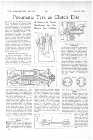
TN patent No. 501,971 by the General !Tire and Rubber Co., Akron, Ohio, U.S.A., is disclosed a clutch design of outstanding novelty. In this scheme the driven member of the clutch consists of a pneumatic tyre, and engagement and disengagement is brought about by controlled inflation. The drawing clearly shows the general arrangement, including the control'valve (1) for inflating and deflating the tyre. This valve also controls a bellows-operated brake (2) for slowing the rotation when gear-changing.
Note.the absence of any co-aligning bearing between the driving and driven members; this is claimed to obviate the need for accurate lining-up during assembly. A further advantage is that torsional vibrations are to a great extent absorbed by the resilience of the rubber tyre.
Utilizing Exhaust-gas Energy.
ASELF-CHARGING oil engine, the exhaust from which is mixed with air and led to a turbine, forms the subject of patent No. 501,981, by •C. Toth, Montevideo, Uruguay. In this design the pistons and cylinders are each of two diameters, a large diameter
3) and a smaller portion (5). • The
upper space (2) is used for pumping air for charging and scavenging. The combustion chamber (7)1.S ring-shaped and can be .opened to the exhaust , port (8) by a piston-valve (6) .
In operation, burning gas from the
combustion chamber flows into the annular space (4) between' the two diameters of the cylinder and piston. This is the power-stroke. At the same time a supercharge of air is conepressed in the upper space .(2). , The rising piston ultimately uncovers ports (1) and the new air, with the exhaust gas, passes into the, exhaust port via the now-open piston-valve (6). The excess of air is heated by the exhaust gas, and the mixture' forms the driving medium of an -eichatist turbine.
. ; An Opposed-piston Swath-plate Engine. •
EXPERIMENTSare still going forward in 'the design 'of swath-plate engines, and in paterit No'. 801,807 is sho'Wn the latest progress in -this direction. The patentee is C. B. Redriip,
ri4(3 Cransley Crescent, Henleaze, Bristol.
In this design there are six parallei cylinders (2), spaced around. a circle, and each containing two oppoSed 'pistons operating on the -two-stroke cycle. A ring of inlet ports (3) is provided at one end of the stroke, whilst ports (I) at the other end: form the .exhaust system. A pair -of wobble-, cianks (5) imparts the reciproc'at'ing motion to the pistons, which are .attached via spherical big-ends (4). The wobble-plates are anchored by cylindrical stubs(6) which slide in parallel guide-ways in the 'casing. Further details are given in patent No. 501,820.
Piston Design for Presswork Production. .
APISTON, designed for production by deep-drawing in light alloy, is shown in patent No. 501,713 by H. Mahle, Pragstrasse 26, Stuttgart-Bad, Cannstatt, Germany. The chief difficulty in such production is the formation of the gudgeon-pin bosses, previous designs having been compelled to incorporate welding.
In the present scheme the first pressing operation produces a piston of the form shown in sketch A; this has two ribs (1) extending from the gudgeon-pin to the crown. Small holes (2) are next drilled and the second press operation is performed; this comprises the forcing of a taper mandrel into the holes (2) which swells the ribs into bosses, as indicated in sketch B.
Distributing Gear on Central Tubular Chassis.
FROM S. A. Adolphe Saurer, Arbon, Switzerland, comes patent No. 501,107, disclosing a design of vehicle now rather popular on the Continent— one with a central tubular chassis member and swinging half-axles. In this case, the chassis member (4) is a boxlike structure, built up, by welding, from sheet metal. At the points where the axles are situated, the box section is enlarged into eyes in order to provide " windows " (5) through which the axle shafts protrude. The engine (1) drives the gearbox (2) which, in turn, drives a distributing gear (3). From this, drive shafts pass along the inside of the chassis to the two live axles. The object of the design is to give the maximum . protection to the -driving rneeliariism.