


A POWER-TIPPING DEVICE.
Page 30
If you've noticed an error in this article please click here to report it so we can fix it.
A Resum6 of Recently Published Patent Specifications.
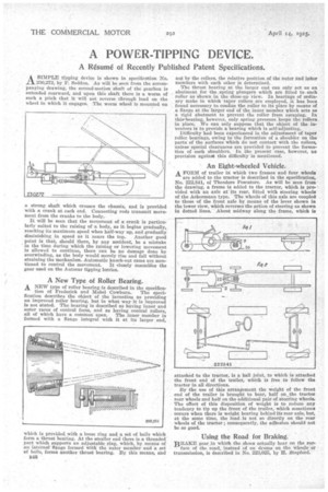
ASIMPLE .tipping device is shown in specification No. 30,272, by F. Seddon. As will be seep from the accompanying drawing, the second-motion shaft of the gearbox is extended rearward, and upon this shaft there is a worm of such a pitch that it will not reverse through load on the wheel in which it engages. The worm wheel is mounted on a strong shaft which crosses the chassis, and is provided with a crank at each end. Connecting rods transmit movement from the cranks to the body.
It Will be seen that the movement of a crank is particularly suited to the raising of' a body, as it begins gradually, reaching its maximum speed when half-way up, and gradually diminishing in speed as it nears the top. Another good point is that, should there, by any accident, be a mistake in the time during which the raising or lowering movement is allowed to continue, there can be no damage done by overwinding, as the body would merely rise and fall without straining the mechanism. Automatic knock-out earns are men
tioned to control the movement. It closely resembles the gear used On the Autocar tipping lorries.
A New Type of Roller Bearing.
A NEW type of roller bearing is described in the specifics. tion of Frederick and Mabel Cowburn. The specification describes the object of the invention as providing an improved roller bearing, but in what way it is improved is not stated. The bearing is described as having inner and outer races of conical form, and as having conical rollers, all of which have a common apex. The inner member is formed with a flange integral with it at its larger end,
which is provided with a loose ring and a set of balls which form a thrust bearing. At the smaller end there is a threaded' part which ,supports an adjustable.ring, which, by means of .au internal' flange formed With the miter menTher and a set of balls, forms another thrust bearing. By this means, and
B46
nqt by the rollers, the relative position of the outer 'and inner members with each other is determined.
The thrust bearing at the larger end can only act as an abutment for the, sprinr, plungers which are fitted toeach roller as shown in the close-up view. In bearings of ordinary make in which taper rollers are employed, it has been found necessary to confine the roller to its place by means of a flange at the larger end of the inner member which acts as a rigid abutment to prevent the roller from escaping. In this-bearing, however, only spring. pressure keeps the rollers in 'plaee. We can only suppose that the objeet of the inventors is to provide a bearing which is self-adjusting.
Difficulty had been experienced in the adjustment of taper roller, bearings, owing to the formation of a shoulder on the parts of the surfaces which do not contact with the rollers, unless special clearances are provided to prevent the formation of such shoulders. In the present case, however, no provision against this difficulty is mentioned.
An Eight-wheeled Vehicle.
A FORM of trailer in which two 'frames and four wheels are added to the tractor is described in the specification, No. 222,841, of Theodore Pescatore. As will be seen from the drawing, a frame is added to the tractor, which is provided with an axle at its rear, fitted with steering Wheels of the Ackermann type. The wheels of this axle are coupledto those of the front axle by means of the lever shown in the lower view, which reverses the action of steering as shown in dotted lines. About midway along the frame, which is attaohed to the tractor, is a ball joint, to which is attached the front end of the trailer, which is free to follow the tractor in all directions.
By the use of this arrangement the weight of the front end of the trailer is brought to bear, half on, the tractor rear wheels and half on the additional pair of steering wheels, The effect of this disposition of weight is to reduce any tendency to tip up the front of the trailer, -which sometimes occurs when there is weight bearing behind its rear axle, but, at the same time, the load is not so directly on the rear wheels of the tractor; consequently, the adhesion should not be so goal Using the Road for Braking. BRAKE gear in which the shoes actually bear on the surface of the road, instead `of on driuns on the wileels or transmission, is described in No. 223,025, by H. Stopfo-rd.