


Patents Completed.
Page 26
If you've noticed an error in this article please click here to report it so we can fix it.
FLEXIBLE COUPLING. — Albion Motor Car Co., Ltd., and another,—No. 23,469, dated November 13th, 1905.—A universal coupling (C), carried by the driving shaft (D), is connected to a sleeve (II) free on the driven shaft (A). That end of the sleeve (B) remote from the
co titling carries one part (E) of a jaw clt tch, and the corresponding part (G) is carried by a collar (H), fast on the driven shaft (A). Connecting the sleeve (B) and collar (H) is a stout spring (J), 'arid the distance between the jaws and the opposed clutch parts is such that each part can move a given distance relatively to the other in either direction of rotation. It will thus be seen that the driving shaft first advances the part (E) of the jaw clutch, and, in so doing, puts tension upon the spring (J), so that a resilient drive is obtained, and the jaw clutch may or may not come into operation. The spring will drive in either direction, but should it break driving can still be effected through the jaw clutch.
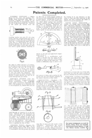
PORTABLE SUCTION GAS ENGINE. — Deutsche Sauggas-I.okomobilWe rke Gesellschaft. — No. 3,146/1906, dated under Convention September 4th, 1905.—The producer (a) is connected with a coal receptacle (ô), whence the coal can slide through an opening (f) to the producer. Beneath the coal receptacle the cooler and purifier (d) is arranged, and the engine (c) is carried on top of the apparatus. The vibration of the vehicle as it travels automatically feeds the coal down to the producer. The orifice (f) may be controlled by a suitable sliding door to regulate the rate of flow.
STEERING WHEEL.—Mercier.—No. 20,792, dated October 13th, 1905.—To absorb vibration, the rim IW) of the wheel is connected to the hub portion by spokes
(ii, the ends of which engage sockets in the rim and hub respectively, and are free to slide therein. At the base of each socket is a spring (6, or al), and, within tubes (1)3 other spiral springs are provided whereby vibration in a lateral direction of the wheel is absorbed. Moreover, the spokes Is) are preferably built up of a number of laminze (1) for the same putpcse. If desired, the spokes may be secured rigidly at one end or the other, as
shown on the left and right-hand respectively of Fig. 1. According to a modification, each spoke is divided into two parts (s5, s6); one part carries a pin (251), which passes through an orifice in the other part. The orifice is sufficiently large to allow a cer tam n amount of play, and a spring (t) surrounds the pin and absorbs vibration in the lateral direction of the wheel.
CARBURETTER. — Shepherd. — No. 16,736, dated August 18th, 1905.—For contolling the the amount of air directed upon the nozzle of a carburetter a resilient conical shield is provided. This conveniently consists of a suitably shaped strip of steel, coiled round upon itself, and supported upon a flange (71) in such posi tion that it surrounds the nozzle of the carburetter, Surrounding the conical shield is a member (p1), which has a screw-thread or other oblique connection (p3), with a suitable fixed member, so that,
by turning it in one direction or the other, it rises and falls relatively to theshield, and thus contracts the latter or allows it to uncoil and expand.
LIQUID LEVEL INDICATOR. — Veulle.—No. 21,242, dated October 19th, 1905.—The level comprises a vertical tube. (A) of transparent material, communicating with a small reservoir (B). Extending from the top of the chamber (B) is a. tube (C), and this is lowered to the bottom of the tank (E), in which it is desired to ascertain the level of the liquid. As thetank (E) is filled the liquid rises in the tube (Di and creates pressure in the chamber (B). This pressure forces the liquid, indicated at c in the chamber (B) up the tube (A), and the height of this column will approximately correspond to the depth of the liquid in the tank. In some uses the liquid in the tank is under pressure, and when this is so a tube (F) is
employed to connect the top of the indicator tube (A) with the upper portion of the tank, whereby the pressure is equalised.
RADIATOR.—Critchley and another.— No. 9,085, dated March 2nd, 1906.—IIeretofore sealed tubes containing a highly volatile spirit have been used as a cooling agent in a horizontal reservoir, but according to this invention the tubes (D) are set obliquely in a vertical reservoir
(1-11. The ends (DI) of the tubes enter the reservoir, and through the oblique setting of the tubes the liquid collects in this portion, and is thus always in close proximity to the water it is to cool. The water enters the chamber (E) by an inlet (Al, and leaves it at (1.1). It is stated that with an arrangement of this kind circulation is automatic, so that, even should the pump break down, the flow of the cooling water will not be interfered with.