


Nutches: 2
Page 25
If you've noticed an error in this article please click here to report it so we can fix it.
;INGLE-PLATE clutches with the :lamping force provided by coil iprings were discussed in my ast article. In recent years, :specially on lighter vehicles, his type of clutch has, in many mses, been superceded by the iiaphragm clutch.
As in the coil-spring type the :entre driven plate is clamped Petween a pressure plate and he engine flywheel, but the lamping pressure is supplied w a diaphragm spring. The :lutch cover, bolted to the Incline flywheel, drives the pressure plate. With the clutch ingaged, as shown in Figure (a) he diaphragm spring forces the Pressure plate towards the lywheal clamping the driven :entre plate between them. Thus he engine, clutch cover, pressure plate and driven plate ill rotate together to transmit he drive to the gearbox.
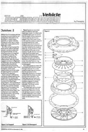
Clutch release is effected by noving the release bearing into :ontact with the release plate vhich in turn applies pressure to he ends of the diaphragm ;wing fingers. The movement of he fingers is transmitted via the ulcrum rings and the retractor :lips and/or drive straps to the pressure plate, moving this may from the driven plate. The lywheel and cover assembly hus revolve alone, not turning he driven plate, and the ransmission is therefore fisconnected (see Figure (b)). Figure 2 gives an exploded view of a 420mm diameter diaphragm clutch. It is fitted with a pressed steel cover (2) and so • that the depth of the pressing is not too great an aluminium • adaptor ring (14) is used. Drive to the cast iron pressure plate (7) is transmitted by four steel straps (3) one end of which is riveted to the cover pressing and the other bolted to the pressure plate lug. A ring of twelve rivets and sleeves firmly secure the support ring (8), the two fulcrum rings (9) and the diaphragm spring (6) inside the cover. When the clutch is in the engaged position the load is carried by the fulcrum ring adjacent to the cover, the other fulcrum ring . carries the load when the clutch is disengaged.
• Four clips (pressure plate) (10) are bolted with the drive straps, through a ferrule (11), to the pressure plate lugs and ensure • that the periphery of the diaphragm spring is in constant contact with the pressure plate • during clutch actuation, The diaphragm spring fingers are curved at the ends, this design enables a degree of release bearing misalignment to be tolerated. The driven centre plate is shown at (15).
The diaphragm spring clutch is more compact than the coil -spring type; there are no long coil springs to accommodate; it is easily balanced; lower pedal force is needed; clamping force does not decrease as linings wear.