 1
1 2
2 3
3 4
4 5
5 6
6 7
7 8
8 9
9 10
10 11
11 12
12 13
13 14
14 15
15 16
16 17
17 18
18 19
19 20
20 21
21 22
22 23
23 24
24 25
25 26
26 27
27 28
28 29
29 30
30 31
31 32
32 33
33 34
34 35
35 36
36 37
37 38
38 39
39 40
40 41
41 42
42 43
43 44
44 45
45 46
46 47
47 48
48 49
49 50
50 51
51 52
52 53
53 54
54 55
55 56
56 57
57 58
58 59
59 60
60 61
61 62
62 63
63 64
64 65
65 66
66 67
67 68
68 69
69 70
70 71
71 72
72 73
73 74
74 75
75 76
76 77
77 78
78 79
79 80
80 81
81 82
82 83
83 84
84 85
85 86
86 87
87 88
88 89
89 90
90 91
91 92
92 93
93 94
94 95
95 96
96 97
97 98
98 99
99 100
100 101
101 102
102 103
103 104
104 105
105 106
106 107
107 108
108 109
109 110
110 111
111 112
112 113
113 114
114 115
115 116
116 117
117 118
118 119
119 120
120 121
121 122
122 123
123 124
124 125
125 126
126 127
127 128
128 129
129 130
130 131
131 132
132 133
133 134
134 135
135 136
136 137
137 138
138 139
139 140
140 141
141 142
142 143
143 144
144 145
145 146
146 147
147 148
148 149
149 150
150 151
151 152
152 153
153 154
154 155
155 156
156 157
157 158
158 159
159 160
160 161
161 162
162 163
163 164
164 165
165 166
166 167
167 168
168 169
169 170
170 171
171 172
172 173
173 174
174 175
175 176
176 177
177 178
178 179
179 180
180 181
181 182
182 183
183 184
184 185
185 186
186 187
187 188
188 189
189 190
190 191
191 192
192 193
193 194
194 195
195 196
196 197
197 198
198 199
199 200
200 201
201 202
202 203
203 204
204 205
205 206
206 207
207 208
208 209
209 210
210 211
211 212
212 213
213 214
214 215
215 216
216 217
217 218
218 219
219 220
220 221
221 222
222 223
223 224
224 225
225 226
226 227
227 228
228 229
229 230
230 231
231 232
232 233
233 234
234 235
235 236
236 237
237 238
238 239
239 240
240 241
241 242
242 243
243 244
244 245
245 246
246 247
247 248
248 249
249 250
250 251
251 252
252 253
253 254
254 255
255 256
256 Eddy-current Braking
Page 202
If you've noticed an error in this article please click here to report it so we can fix it.
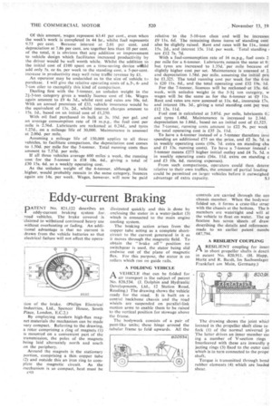
pATENT No. 821,122 describes an eddy-current braking system for road vehicles. The brake covered is
• claimed to withstand continued heavy use without overheating or fading. An additional advantage is that no current is drawn from the vehicle batteries so that electrical failure will not affect the opera tion of the brake. (Philips Electrical Industries, Ltd., Spencer House, South Place, London, E.C.2.) By employing modern high-flux magnet materials the mechanism can be made very compact. Referring to the drawing, a rotor comprising a ring of magnets. (1) is mounted on a convenient part of the transmission, the poles of the magnets being laid alternately north and south on the periphery.
Around the magnets is the stationary portion, comprising a thin copper tube (2) and outside this an iron ring to complete the magnetic circuit. As the mechanism is so compact, heat must be c60 dissipated quickly and this is done by enclosing the stator in a water-jacket (3) which is connected to the main engine cooling system.
The braking action arises from the copper tube acting as a complete shortcircuit to the current generated in it as it moves through the magnetic field. To obtain the "brake off" position no switchgear is used, the stator being slid endwise out of the plane of magnetic flux. For this purpose, the stator is on rollers which run on guide rails.
A FOLDING VEHICLE
I-I A VEHICLE that can be folded for
air transport is the subject of patent No. 820,534. (1. Dolphin and Hydraulic Developments, Ltd., 12 Station Road, Reading.) The drawing shows the vehicle ready for the road. It is built on a central backbone chassis and the road wheels are suspended on parallel-link motion arms to enable them to be raised to the vertical position for stowage above the frame.
The bodywork consists of a pair of punt-like units; these hinge around the tubular frame to fold upwards. All the controls are carried through the cen chassis member. When the bodywor folded up, it forms a crate-like state' with the chassis at the bottom. The b members are watertight and will al the vehicle to float on water. The sp fication has seven sheets of draw; describing the details and references made to an earlier patent numb( 687,794.
A RESILIENT COUPLING
PAA RESILIENT coupling for inseri in short propeller shafts is descri in patent No. 820,911. (H. Happ, Hartz and R. Bardt, Im Sachsenlager Frankfurt am Main, Germany.)
The drawing shows the joint which located in the propeller shaft close to fork (I) of the normal universal jo The latter drives an inner member cat log a number of V-section rings Interleaved with these are inwardly p jecting rings (3) fixed to. the outer casi which is in turn connected to the prop& shaft.
Torque is transmitted through bond rubber elements (4) which are loaded shear.