


SLEEVE-VALVE ENGINE DESIGN.
Page 48
If you've noticed an error in this article please click here to report it so we can fix it.
A Résumé of Recently Published Patents.
SOME INTERESTING details of the Wallace sleeve-valve engine are disclosed by Wallace (Glasgow), Ltd., and W. Guthrie, in specification No. 204,522. The invention is chiefly concerned with the method of driving the sleeve valve and the means for lubricating the engine. The crankshaft, which is carried in two ball bearings, drives the sleeve-valve shaft through gearing at the same rotational speed, the necessary two-to-one reduction in gearing between that shalt sad the valves themselves being effected in the moaner to be explained.
At suitable intervals along the sleeve driving shaft are skew pinions, each of which engages with a skew wheel having deuble the number of teeth, and mounted an a short, transverse member, which at its inner end has a crank pia upon which is mounted a ball which is free to move endwise. The ball ezigages with the interior of the outer race of a ball bearing which is secured in a boss on the side of the valve, near its lower edge. The effect of this arrangement is that the valve receives a combined rotary and reciprocating Motion, with a period double that of the crankshaft.
The rear end of this sleeve-valve driving shaft engages with the spindle of a rotary pump, which 'draws oil from the crankcase sump through a substantial gauze filter and past a non-return valve, delivering it into a horizontal pipe mounted inside the crankcase and provided with nozzles which direct the oil into troughs, one below each connecting rod. The troughs are partially covered by baffle plates to prevent unnecessary splashing,ofsthe oil. The pump itself is so designed that a small quantity of the oil which passes through it overflows into the cylindrical casing of The sleeve-valvedriving shaft. It flows along the length of this shaft, passing through suitable apertures in its bearings, lubricating those bearings and the skew gears, and, finally, emerging into the timing case to oil the gears.
Other Patents of Interest.
Certain details of an improved, design of six-wheeled tractor-trailer vehicle are disclosed in specification No. 204,690 by Richard Garrett and Sons, Ltd. The connection between the intermediate axle and the rear axle is a plain link, which is attached at each end to pins above the eentres of those axles. A rod rigidly coupled to the rearmost axle projects forward, and is forked at its front epd to engage a rearwardly projecting pin on the frame of the tractor. The effect of this arrangement is that, as the tractor turns on a corner, the rearmost axle is so controlled that its wheels follow in the track of those of the front and intermediate axles.
A. E. Osborne combines an epicyclic gear with the builtup crankshaft of his engine. Both crankshaft and crank pin ‘considering this invention as applied to a single-cylinder engine) are hollow. One portion of the crankshaft carries a central spindle, which at its outer end is keyed to one part of a friction clutch end, at its inner end, carries a pinion. The latter engages with a wheel which is secured to one end ef a spindle, which takes its bearing inside the hollow crank B56
pin, the said spindle having, at its Other end, another gearwheel, which meshes with a fourth pinion keyed to the inner end of a shaft which is supported inside the other portion of the crankshaft, and which carries, at its outer :end, the main driving sprocket Or pinion for final transmission of the engine power to the axle of the vehicle. leThe other member of the friction clutch to which we have referred is keyed to the crankshaft proper. If the two members of the cluteh are in engagement, the gears arelocked solid and the drive is a direct one ; if they are disengaged, and the outer member held by means .of a brake, then trariamission takes place through the medium of the gears which have been enumerated. This invention is described in detail in specification Ne. 204,616.
A piston with a loose head is described by C. W. Kerridge in specification No. 204,524. This head, which is secured to the skeleton piston by a setscrew and nut, supports the rings, so that in the case clf an engine with detachable head this portion of the piston, with the i•ings, can be removed and cleaned during the process of decarbonizing.
A simplification in the design of a rear live aele is embodied in specification No. 204,519 b,y C. F. Vaughan. The axle case itself is in one piece front end to end, and has no rear covering. It has a large aperture towards the front, which is closed by a cover which supports the whole of the differential gearing as well as worm and Wheel of the final drive. The arrangement is such that, notwithstanding the absence ef any split bearings or housings, all the gears can be entirely dismantled or assembled into this covercasting with cue and rapidity.
In the epicyclie change-speed gear which is described in epeciffeatien'No. 204,247 by D. Wier, the change of gear is effeeted by control of the rotation of the planetary pinions, each of which is formed of several thin plates, separated from one another by others which are so designed that with the aid of a spring and suitable operating mechanism, they operate as a miniature multi-disc clutch.
R. G. Hawkins and another describe *an arrangement of unclerslung transverse spring, secured at its centre to the frame of the vehicle and coupled, at its ends, by shackles, to the underside of the axle, clearance . for its movement being afforded by offsetting this body of the axle.
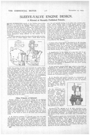
In the suspension system which is described in specification No. 204,57E3 inicumatie chambers, of various heights, are mounted on a. platform which is secured to the top of the axle. These chambers make contact successively with the underside of the vehicle as the load or shocks to which it may be subjected are increased. The patentee is C. 11igne.
Specification No. 198,46E3, by F. E. Ellis, describes a combined turntable and tipping gear, so designed that tipping may take place to each side, to the rear of the vehicle, or in any intermediate direction. A circular bracket is secured to the chassis of the vehicle, and within this a turntable may revolve.
The turntable is made from channel steel. Its lower flange is supported on rollers, which are carried by the bracket on the frame of the c.haesis. To its upper fiance are secured two longitudinal bearers. A shaft atmlbne erea of these is the hinge about which the body is tipped. At the other end tha tipping gear is carried. The turntable, in point of fact; intervenes between tipping gear and chassis, allowing it to operate in all the directions named.