


SWEEPING AND COLLECTING SIMULTANEOUSLY.
Page 27
Page 28
If you've noticed an error in this article please click here to report it so we can fix it.
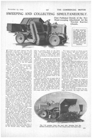
IT WAS with great interest,' that t‘e recently inspected, and had a short. trial run on, the latest development in road-sweeping appliances produced by Karrier Motors, Ltd. This is a remarkably neat, simple and efficient machine, which performs the triple functions of sprinkling, sweeping and collecting the swept material into its own body, from -which, incidentally, it can -be tipped with the greatest ease.
The builders have had unique experience in the construction of sweepers, combined with conveyors, for the detritus, and their large machine was accorded an excellent reception. The new sweeper has been built to meet the needs of those municipalities which do not wish to go to the expenditure entailed by. purchasing the large' type, or which are of a:size not necessitating a machine of such large capacity.
What, may be termed the foundation of the new sweeper is a 2-ton, C-type Karrier chassis, slightly. modified as regards its final drive, which is by overhead worm gear, giving :a ratio of 10-1, whilst the gearbox gives three speeds of 3, 6 and 10 m.p.h. at the normal engine revolutions. Between the front and rear wheels of this chassis is the brush, suspended by two independently balanced radius arms, and set atan angle across the chassis, so that the near-side end of the brush is in advance of the other end.
The mechanically operated conveyor is immediately in front of the off-side end of the brush, and set parallel to it. This conveyor consists of three rotors, each carrying four brush arms, and the middle rotor Devolves in the opposite direction to the other two. , The roter brushes are adjustable for wear' and access to them is obtained through large hinged doors in the conveyor case. A. cross-shaft is -utilized .for driving both the -sweeping. brush and the conveyor; thisshaft takes its power from the layshaft of the vehicle gearbox through the medium of a worm gear, and at -its mater end is a *rely flexible coupling, to Which is connected a short shaft, passing freely through the centre of the bottom conveyor rotor, and terminating in,twre chain sprockets, one of which &Hires the brush -whilst the other drives the top and middle rotors.
At the inner side of the top rotor is another sprocket, and this conveys power to the bottom rotor, which, together with its sprocket, floats on the drive shaft. This arrangement is adopted in order to obtain a higher speed than could be secured by taking the drive direct to the bottom rotor and from it to the others.
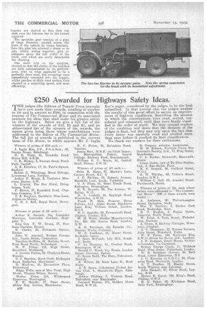
To obtain an adequate idea of how the collector operated it is necessary to revert to the brush. This is built up of six segments, with straight bristles, and a rose-piece at the near-side end. The ros3-piece cleans the gutter direct, and the sweepings are carried from the kerb face towards the other end of the brush, where they are thrown on to the collector rotors, and lifted by these into the tip_ ping licidy of the machine. Suitable metal guards are fitted to shield the mechanism of the chassis from splashing, and these can be adjusted closer to the brush as this wears.
The brush radius arm at each side is separately supported, or partially so, by two long coil tension 7 springs, the pull of which is adjusted by means of a small handwheel, so that only a part of the weight of the brush bears on the road surface, whilst the independent suspensaon of each end enables the brush to have even contact with the road over the full swept width of 7 ft.
Two types of body are fitted, according to whether the water sprinkler is
acquired or not. When wanted, the water tank -is carried, behind the refuse hopper, which is then arranged for tipping to the near side. Where no tank as necessary, the hopper can be fitted for end tipping.
In order to Meet all conditions of road cleansing the hopper is'built of wood,
lined with steel. In the side-tipping type it is supported by rollers on an angle steel frame, bolted to the chassis frame. Pivoted to the centre of the off side of the hopper is a Steel link rod, which is a sliding fit in a fork end, itself permitted to move across the chassis on a cross-bar. Between the fork end and a collar on the link rod, are two strong tensionsprings, which absorb the shock caused by the arresting of the hoppar at the end of its tip. :
Normally, the 'hopper is locked in position by ,a spring bolt, but when this is released the hopper can he pushed along its runners until it passes the balancing point, when it tips over to ar angle which is sufficient to give an absolutely clean discharge.
To permit, and also to limit-, the side ways movement, the angle steel body bearers are slotted so that they can slide over the fulcrum bar to the extent required.
• The sprinkler gear consists of a pipe of large diameter, carried across the front of the vehicle by frame brackets. Into this pipe are screwed a dozen or so jets, which, acting together, give an adequate spray the full width of the track, and which are easily detachable for cleaning.
Our short trip on the machine, showed us that the claims of the builders are fully substantiated by its performanee, even on what appeared to be a perfectly clean road, fine sweepings were immediately conveyed into the hopper, whilst patches of dirty road surface were cleaned at a surprising speed, and most
efficiently. ,