Patents Completed.
Page 24

If you've noticed an error in this article please click here to report it so we can fix it.
Adjustable Roller Bearings. L.G.O.C. Bodies. Worm-drive Lubrication.
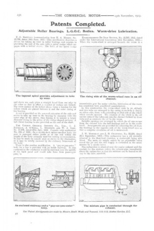
F. G. BRETTALL (communication from H. A. itIvrias), No. 13,795, dated 14th June, 1913.—This specification describes a device for taking up wear in roller bearings and consists in providing the end of the axle with a spiral wedge which engages with a helical sleeve. The helix of the spiral wedge The tapered spiral provides adjustment to take up wear.
and sleeve are each given a. straight bevel from one edge to the other so that in effect a number of wedgesare formed. The outer surface of the helical sleeve forms a bearing for the rollers which are placed between it and the outer casing of the bearing.
A nut is provided on the screwed extension of the axle and serves to take up wear in the bearing by engaging with the outer edge of the sleeve, thus forcing it to assume a larger diameter owing to the action of the wedge-shaped surfaces. A ball thrust-bearing is also provided on the end of the shaft.
THE LONDON GENERAL OMNIBUS CO., LTD., G. J. RAcKuAm, J. O'NEILL, L. AlitlssEnvv AND W. J. InEN, No. 17,476, dated 27th July, 1912. Cognate with application No. 216 of 1913.—In a double-deck motor-omnibus body the stair is arranged either inside or at one end within the length of the body nermally used for seating accommodation. It may be made an outside stair as shown in the illustration, or it may be totally enclosed by the crdinary framework of the body
There is also another modification. A pay-as-you-enter" body for a bus is provided with an inside stairway. In this construction the conductor would be stationed near the middle of the back panel and would take fares from passengersgum' io
ETABLISSEbriENTS DE DION BOUTON, No. 12,362, 1913, dated under the International Convention 11th November, 1912.— When the worm-wheel is arranged beneath the worm in a
The rising side of the worm-wheel runs in an oil
channel.
. • .
transmission var for motor vehicles, lubrication of the worm has sometimes been considered unsatisfactory.
In this construction the worm-wheel runs in an oil-bath and two webs are arranged in the casing to encircle it closely on either side, these webs extending on that side of the wheel which travels upward The rotation of the wheel in the oil carries some of the lubricant into the channel formed by these webs and so conducts the oil to the worm.
Suitable openings are arranged by which the oil can escape from the channel into the ball-bearings and on to the worm itself. Arrangements are provided for returning the oil from the bearings to the opposite side of the worm-wheel case so that a complete circulation of oil is maintained.
J. W. MOWBRAY AND J. H. CHANmEss, No. 22,239, dated 30Lli September, 1912.—This carburetter has a jet centrally situated in the float-feed chamber, a choke-tube being also fitted. The main air supply enters by an adjustable valve round the jet and the fuel supply is controlled in the usual manner by a needle-valve.
'rho carburetter is situated near the engine exhaust and the conduit for the mixture enters the exhaust-pipe immediately above the carburetter so that the mixture can be heated on its vay to the inlet manifold.


