


Drivers &Mechanics
Page 22
Page 23
If you've noticed an error in this article please click here to report it so we can fix it.
Light Up Your Lamps At — 5.13 on Thursday ; 5.12 on Friday ; 5.11 on Saturday; 5.8 on Monday ; 5.6 on Tuesday ; 5.5 on Wednesday.
Making Up a Worn Shaft.
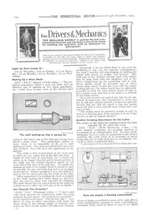
[1377] " S.F.C." (Queen's Park) writes :—" The following description which I send you deals with an effective way of making up live axles, gearshafts, etc., which have become worn at the bearing part
The split making-up ring is sprung on.
owing to the inner ring of the ball race having been fitted a shade slack. This particularly applies to cases where it is impossible to fit an a solid making-up bush. The enclosed sketch [We have had this redrawn.—En.] will show the application of my method.
"The shaft is first turned down at the worn part to about an in. under size of the ball-s ace bore. A length of steel tube of convenient size is bored out about .01 in. bigger than the newly turned portion of the shaft, and the outside diameter should be left TV, in. full of the bore of the ball race. To enable the making-up bush to be readily fitted it should be split at one side, the saw cut being best put in at an angle of 43 degrees. Before springing it over the shaft it is best to tin the latter and also the inside of the tube.
"After expanding it in position the bush is sweated to the shaft, making sure whilst doing so, however, that the saw-cut edges butt together by clamping. The shaft should the.n be turned down at the made-up portion so as to allow the ball race to fit on tightly."
Are Tractors Too Powerful ?
[1378] " G.D." (Poynings) writes :—" I have read with much interest the controversy which has been going on in your paper 'Are tractors too powerful? or as I myself would query Why do they slip ?' As a driver of some 14 years' experience with many big firms using all the leading makes of tractor*, probably my views on the matter will add_some interest.
"Personally I do not think there is any need foi modifying in any way the drawbar arrangements, but what I consider will stop slipping is building the engine with plenty of weight well forward. The back end of the cylinder casting ccadd with advantage be built flush with the smokebox end of the botler, lengthening up the connecting rods to suit. Three speeds should be provided, one of which should allow about 01 mile per hour with the engine working full out ; the latter would then be sufficiently powerful to work the road wheels slowly enough to get a proper grip, and this to my mind is a solution of the whole matter.
" As a rule tractors a-re geared too high for all conditions of road-work ; the consequence is, when you get on soft and slippery ground you have to open the throttle full out, and the result is that the tractor starts of with a rush, and the road wheels have not time to bite.
"The engine must be powerful enough to pull its load at a crawling pace if the machine is to be of any service on soft or slippery ground."
Another Grinding Attachment for the Lathe.
The sender of the following communication has been awarded the 10s. prize this week.
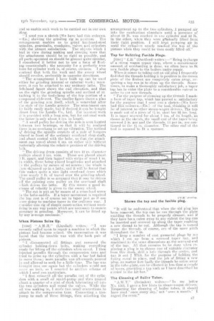
[1379] " H.34." (West Bromwich) writes:—' In most modern workshops the grinding machine is recognized as an indispensable tool. In some establishments, however, such an equipment is not always installed, the work which it is necessary to grind being sent out to some local firm to be treated ; the result is often considerable delay.
"I am employed in a shop myself in which this eon Does not employ a floating countershaft.
dition of things prevailed for some while, and, after a little consideration, decided to make a grinding atrtachment which could be fitted to one of our lathes
and so enable such work to be carried out in our own shop.
" I send you a sketch [We have had this redrawn. —En.] shciwing the grinding rig in position. The arrangement enables us to grind hatdened-steel spindles, ge.arshafts, crankpins, valves and cylinders with the utmost satisfaction. The objects which I had in view during making and erecting were that the attachment should be as rigid as possible, and all parts operated on. should be ground quite circular, considered it better not to use a form of floating countershaft; the necessity for .a perfectly true bore for cylinder work is, of course, obvious. I also contend that both the work and the emery wheel should revolve, preferably in opposite directions.
" The arrangement I have built up can be used either for grinding internal or external woik ; moreover, it can be attached to any ordinary lathe. The left-hand figure shows the end elevation, and that On the right the grinding spindle and method of attaching it to the tool-clamp of the top portion of a compound slide-rest. The smaller figure shows a plan of the grinding arm itself, which is somewhat after tie style of the Landis grinder. The attachment can he fairly easily made, hut if desired it can be bought direct. from the Landis Co., Ltd. For internal work it is provided with a long arm, but for external work the latter is only about 3 ins, in length.
" A small pulley for driving the arm is seen located between two bearings, so that it will be realized there is no overhang to. set up vibration. The method ,af driving the spindle consists of a pair of hangers ulaced in front of the ordinary overhead shop-shaft, and about central with the lathe, so that. theattachment can travel about 6 ins, on either side without materially altering the relative position of the driving belt.
" The driving drum consists of two 19
diameter pulleys about 2 ins. wide. These are placed about 3 ft. apart, and then lagged with strips of wood I in in width, these being placed lengthwise and attached do the pulleys by means of set-screws ; the whole is ,Liten skimmed up in a lathe, and it will be found that this makes quite a nice light overhead drum which rives nearly 3 ft. of travel over the grin4ling-wheel. The small pulley is so arranged that it may be driven off the existing cone pulley on the overhead shaft vitich drives the lathe. By this means a goad increase of velocity is given to the emery wheel.
'The cut is put on by means of a cross-feed screw in the lathe-saddle. If a taper movement is required the top rest is of course set to taper jusf as if one were going to machine taper in the ordinary way. I consider this rig of simple construction -without sacrificing in any way .points which are necessary to ensure accuracy in grinding. Moreover, it can be fitted up by any average mechanic."
When Pistons Seize Up.
[1380] " (Llanaaff) writes :• I was recently called upon to repair a machine in which the pistons had become seized. On examination it was found that the trouble was with the back pair of Listons.
" I disconnected all fittings and removed the cylinder holding-down bolts, making everything ready for lifting off the cylinders when eased. I then injected paraffin through the compression taps and tried to prise up the cylinders with a bar but failed to move them; more paraffin was afterwards poured in and allowed to soak for a little time. The bar was brought into use again hut the cylinders would not move an inch, so I resorted to anothee scheme of which I send you particulars.
" I first removed all the paraffin out of the cylinders with a small oil squirt-pump and then poured about a quarter of a Dint of thiek lubricating oil into the two cylinders and round the valves. While the oil was soaking in, I made two small connections to attach to the compression taps. Connecting a tirepump to each of these fittings, then .attaching the
arrangement up to the two cylinders, I pumped air into the combustion chambers until a pressure of about 00 lb. was reached in one cylinder and 80 lb. in the other, when they were gradually lifted from their tight position. 1 still kept pumping air in until the cylinders nearly reached the top of the pistons when they could be then easily lifted off."
Tap for Refitting Fusible Plugs.
[1381] " E.B." (Dartf.ord) writes :—" Being in charge of a steam wagon repair shop, where a considerable amount of overhauling is done, we often have to fit new fusible plugs to the boilers under repair.
When it comes to taking out an old plug I frequently find that the threads holding it in position in the crown plate of the firebox are completely eaten away, requiring a tap run in to clean up the threads. Sometimes, to make a thoroughly satisfactory job, a taper tap has to enter the plate to a considerable extent in order to Cult new threads.
" For the purpose of cleaning up the threads I made
form of taper tap, which has proved so satisfactory for the purpose that I send you a .s.keten—[We have had this redrawn.—Enje of the tool, thinking it will be of interest to ether steam-wagon drivers. The tap is made out of a piece of i in. steel bar 9 ins. long. It is taper serewed for about 7 ins, of its length, as shown in the sketch, the small end of the taper being screwedfst in. gas and the threads, 14 per in., are continued to the 11 in. diameter. The other end of the tool is squared to fit a spanner.
Shows the tap and the fusible plug.
"It will be understood that when the old plug has been removed, the tap can be run through the plate enabling the threads to be properly cleaned, and if they have been eaten away to any extent the tap can be inserted and screwed up along the taper enabling a new thread to be cut. Although the tap is turned taper. the threads, of course, are of the same pitch throughout the 7 in.
" I keep a number of cast gunmetal plugs by ire which I cut up from a screwed taper bar, and machined to the same dimensions as the screwed end of the tap. All that remains to be done when replacing a plug is to choose one of suitable diameter from this stook, drill a hale through the centre, and tap it. out el Whit, foT the pill-pose of holding the fusing metal in place, and the job of fitting a new plug, no matter how badly the threads be eaten away in the tube-plate, can be effected in less than a couple of hours, providing a tan such as I have described be carried in the kit-box."
The Cleaning ()I Boiler Tubes (Swindon) writes :—" In my letter No. 1303, I gave a few hints to steam-wagon drivers. Respecting the cleaning of boiler tubes, it should have read once every day,' not once a month.' I regret. the error."