


on, Drivers &Mechanics
Page 21
If you've noticed an error in this article please click here to report it so we can fix it.
TEN SHILLINGS WEEKLY is paid for the best coranrkunication received, and one penny a line of ten words for anything else published, with an allowance for photographs.
Light Up Your Lamps At 8.39 on Thursday ; 8.40 on Friday; 8.42 on Saturday • 8.44 on Monday ; 8.46 on Tuesday ; 8.47 on Wednesday.
Preventing Oil Leakage.
The sender of the following communication has been awarded the Ws. prize this week.
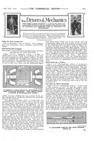
[1626] "E.C.0." (Lytham) writes :—" I had recently sorne .trouble owing to a. leakage of oil from the back bearings of a four-cylinder engine. No matter haw' carefully the oil supply was regulated, there always seemed to be a considerable amount of waste from this source. Besides the expense owing to the oil lost in this way, there was the additional aggra
ration of always finding the rear portion of the engine smothered in oil thrown off from the circumference of the flywheel. "On taking the engine down, I found that the crankshaft had been provided with a thrower ring for the express purpose of preventing the oil from travelling along the shaft to the flywheel. As will be seen from the sketch enclosed [We have, had this redrawn.—En.] this device was quite a successful one up to a point. Any oil which ran from the back bearings of the engine was thrown off by this ring ; some of it would run hack again to the sump, and it was no doubt intended that. all of the surplus oil should so run. Quite a considerable quantity, however, would gather on the inner surface of the shell covering the bearing and run thence to a point on the crankshaft beyond the thrower ring. The only way for the oil after that was along the crankshaft to the flange to which the flywheel was attached, and from there to the flywheel and interior of the bonnet as has been said. All that was needed was something to collect this portion of the oil, lead it away from the crankshaft and back again to the sump. " In order to effeef' this I made a small eplasher
from sheet brass which was, in the end-on view, of a horse-shoe shape and was riveted to the top half of the crankcase and bent flack along its edge, so as to form one half of a trough or gully of which the crankcase casting formed the other portion. From a reference to the illustration, it will readily be gathered that this method accomplished the desired end. The oil which ran down the surface was, by this contrivance, gathered and directed below the crankshaft into the main passage to the sump. The device proved most successful, and our under-the:bonnet 'state of cleanliness is frequently subject for remark to those who knew its appearance in our pte-Splasher days."
Good Work by a Foden.
[1627] "I.E." (Tewkesbury) writes An account of the work performed by a five-ton, steel-fired Foden, owned by a flour miller, may be interesting. The particulars I have sent you cover a period of 60 weeks, and the mileages do not include the return journeys when empty. During this time I have had no tronkle at all, and I think this is a fairly good recorcklas some of the roads over which Itravel ate-very roitgh indeed, and traverse some very steep hills. The loaded mileage covered during the period referred to was 7743, the Ibad carried being 2698 tons. The maximum of useful Miles run during any One week is 19.2, the minimum 54.'
For Ease in Valve Grinding.
[1628] `.` W.A.V." (Finsbury) writes —"I have seen in the columns of your 'D. and M.' pages many descriptions of -different methods of lifting a valve from its seat when it is in process of beii/g. ground. The more common form is that of a, light spi-ing inserted under the valve and resting on the top of that portion of the guide which projectsdnto the cylinder casting. In the shop where I am employed We have all our valves tapped I in. Whitworth in the centre of the head. To fit this we make a sill toa from in. bar steel screwed-1in. Whitworth at one end and shaped at the other end to form a handle.' The sketch which I enclose [We have had this redrawn. ED.] will illustrate my meaning. With sueh a tool it is possible to lift a valve and give it an occasional turn, without any of the additional accessories which are so frequently suggested for the purpose."