


Patents Completed.
Page 22
If you've noticed an error in this article please click here to report it so we can fix it.
Complete specifications of the following patents will be sent to any address in the United Kingdom upon receipt of eightpence per copy at Sales Branch, Patent Office, Holborn, W.C.
INTERNAL COMBUSTION ENGINE. -Martin and Anaher. — No. 10,981, dated 21st May, 1908.—According to this invention two cylinders are arranged horizontally one above the
other ; they are open at both ends, and each has two pistons opposed to one another. The pistons at the right-hand side of the cylinders are connected together by means of a cross beam, and the pistons at the left hand side are connected together in a like manner, The cross beams slide in suitable guides, and impart their reciprocating motion by means of connecting rods to a crankshaft disposed between the cylinders. The inlet and exhaust valves are arranged midway of the length of the cylinders, and are operated, as usual, from the crankshaft through suitable gearing and cam mechanism. In operation an explosive mixture is drawn into the cylinders by the outward stroke of the pistons. It is then compressed and ignited, the explosion in both cylinders taking place simultaneously. The object of this invention is La obtain a more perfectly-balanced engine,
MOTOR VEHICLE.—Sawyer,—No. 8,537, dated 16th April, 1908.—According to this invention the engine, gearbox and differentia' gear are enclosed within an oil-tight casing and mounted upon the front axle. The casing is formed with separate compartments for the engine, variable speed gear, etc., and terminates at each end in forked extenaions which are adapted to receive the swivel pins of the road-wheel journals, The front road wheels are driven from the front axle by means of universal joints or couplings in order to allow them to he turned on their pivots.
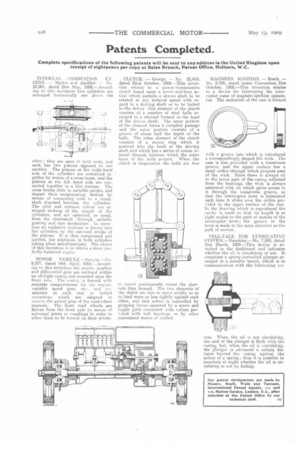
CLUTCH. — George. — No. 22,419, dated 22nd October, 1908.—This invention relates to a power-transmission clutch based upon a screw-and-bore action which permits a driven shaft to be rotated at any reduced speed with regard to a driving shaft or to be locked to the driver One element of the clutch consists of a number of steel balls arranged in a channel formed in the head of the driven shaft, The inner portion of the channel forms a complete passage and the outer portion consists of a groove of about half the depth of the balls. The other element of the clutch consists of a strong ring which is screwed into the bead of the driving shaft and which has a series of coarse internal threads between which the outer faces of the balls project. When the clutch is inoperative the ballsare free
to travel continuously round the channels thus formed. The two elements of the clutch are free to move axially so as to bind more or less tightly against each other, and this action is controlled by gripping levers operated by a screw and toggle joint connected with collars provided with ball bearings, or by other convenient means of control. MAGNETO IGNITION. — Bosch. — No. 3,759, dated under Convention 31st October, 1908.—This invention relates to a device for lubricating the interrupter cams of magneto-ignition apparatus. The underside of the cam is formed with a groove into which is introduced a correspondingly shaped felt wick. The cam is also provided with a transverse groove, and the upper surface has a small orifice through which projects part of the wick. Since there is always oil in the lower part of the casing collected from the bearings, the wick is always saturated with oil which gains access to it through the transverse groove, so that the interrupter lever is lubricated each time it slides over the orifice provided in the upper surface of the cam. In the drawing which is reproduced the cavity is made so that its length is at right angles to the path of motion of the interrupter lever ; the groove in the lever is made in the same direction as the path of motion.
TELL-TALE FOR LUBRICATING SYSTEM,—Maudslay.—No. 7,080, dated 31st March, 1908.—This device is attached to the dashboard and indicates whether the oil is circulating or not. It comprises a spring-controlled plunger arranged in a suitable barrel, which is in communication with the lubricating AyEl tern. When the oil is not circulating, the end of the plunger is flush with the casing, but, when the oil is circulating, the plunger is advanced a certain distance beyond the casing against the action of a spring; thus it is possible to ascertain at night whether the oil is circulating or not by feeling.