Replacing the Cooling Fan by a Blower.
Page 11

If you've noticed an error in this article please click here to report it so we can fix it.
APARTICULARLY interesting engine-cooling system is embodied in the latest chassis produced at the Mack works. The arrangement of the radiator on this make somewhat resembles that on the Renault, in 80 far as the radiator is situated close in front of the dash and behind the engine.
In former models the cooling air was :circulated through this radiator by means of a vaned flywheel, but in the new A.C. model this has been replaced by a blower of the usual centrifugal type, which is held to the rear face of the flywheel by 12 setscrews.
The new radiator consists of two nests of square-finned vertical tubes, each approximately 2 ft. long and of. .1n. tn.
diameter, joined at their upper ends by a particularly strong cast aluminium
• header provided with removabley plates immediately over the tube blocks, 150 that these can be cleaned or examined when necessary.
The header and tube blocks form an arch over the blower, and the small separate bottom tanks are connected together by means of a copper tube of large diameter.
" In order to provide the necessary blast of air through the, tube. interstices, the blower is surrounded by an aluminium cowl or air lead with a deflector, which is so arranged that the draught is divided between the two tube blocks.
The forward side of the cowl fits snugly against the crankcase, but the rear face is provided with an opening, circular in shape and of such a size that it permits air to enter the blower, whilst preventing the expelled air from eseap7: mg except via, the tube blocks.
Before entering the blower the air has to pass through filters, so that any risk
of damage occurring through the entry -of solid foreign matter is obviated.
The blower itself has a diameter of 1 ft. 81 ins., is provided with 60 vanes. and, being driven direct by the engine, does not cause the complications of special bearings, driving gears, or belts.
In the radiator there are 112 tubes, arranged in two•blocks of 56, eight rows with seven tubes to the row.
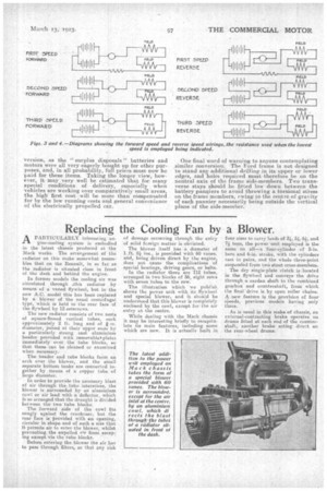
The illustration which we publish shows the power unit with its flywheel and special blower, and it should be understood that this blower is completely enclosed by the cowl, except for the air entry at the centre.
While dealing with the Mack chassis it may be interesting briefly to recapitulate its main feattires, including some which are new. It is actually built in
four sizes to carry loads of 4, 4 4 and 7i tons, the power .unit employed is the same on alla four-cylinder of 5-in. bore and 6-in, stroke, with the cylinders cast in pairs, and the whole three-point suspended from two stout cross-members.
The dry single-plate clutch is located in the flywheel and conveys the drive through. a cardan shaft to the combined gearbox and countershaf t, from which the final drive is by open roller chains. A new feature is the provision of four speeds, previous models having only three.
As is usual in this make of chassis, an external-contracting brake operates on drums fitted at each end of the countershaft, another brake acting direct on the rear-wheel drums.


