 1
1 2
2 3
3 4
4 5
5 6
6 7
7 8
8 9
9 10
10 11
11 12
12 13
13 14
14 15
15 16
16 17
17 18
18 19
19 20
20 21
21 22
22 23
23 24
24 25
25 26
26 27
27 28
28 29
29 30
30 31
31 32
32 33
33 34
34 35
35 36
36 37
37 38
38 39
39 40
40 41
41 42
42 43
43 44
44 45
45 46
46 47
47 48
48 49
49 50
50 51
51 52
52 53
53 54
54 55
55 56
56 57
57 58
58 59
59 60
60 61
61 62
62 63
63 64
64 65
65 66
66 67
67 68
68 69
69 70
70 71
71 72
72 73
73 74
74 75
75 76
76 77
77 78
78 79
79 80
80 81
81 82
82 83
83 84
84 85
85 86
86 87
87 88
88 89
89 90
90 91
91 92
92 93
93 94
94 95
95 96
96 97
97 98
98 99
99 100
100 101
101 102
102 103
103 104
104 105
105 106
106 107
107 108
108 109
109 110
110 111
111 112
112 113
113 114
114 115
115 116
116 117
117 118
118 119
119 120
120 121
121 122
122 123
123 124
124 125
125 126
126 127
127 128
128 129
129 130
130 131
131 132
132 133
133 134
134 135
135 136
136 137
137 138
138 139
139 140
140 Simple Pg1 by Preceptor
Page 87
If you've noticed an error in this article please click here to report it so we can fix it.
pition, 6
E-TIMING THE ignition on an 'gine presents a problem to e inexperienced apprentice Jt if the job is carried out rstematically it is a relatively mple operation. For our scussion let us suppose that it required to replace the stributor on an engine with hich we are not familiar, for hich no workshop manual is ,ailable, we do not know the .ing order and the plug leads we been removed from the stributor cap. In other words e have to start from scratch. The order in which the linders fire must first be termined by removing the cker cover, turning the engine ter and noting in what order e exhaust valves open.
Quite obviously the firing der will be the same as the der in which the exhaust 'Ives open. On modern
!hides no starting handle is ovided and this makes it more fficult to turn the engine. This fficulty can usually be
,ercome by using a spanner (a Icket spanner with a rachet tachment is very convenient)
on the nut or set screw which ecures the fan belt pulley to the crankshaft.
If this is not possible the vehicle can be pushed along slowly in top gear. Removing the sparking plugs so that the engine has no compression will make the engine easier to turn.
Which is exhaust and which is inlet valves can be determined by examining the layout of the exhaust manifold. Usually it is quite easy to follow a branch of the exhaust manifold and to see how it lines up with the valve that feeds it. On many fourcylinder engines the exhaust vales are numbers 1,4, band 8 but this is not necessarily the case. Wiping the rockers clean and marking the exhaust ones with a piece of chalk will make the task easier especially if one is working on one's own.
The engine must now be turned so that number one cylinder is on its firing stroke that is when number one piston is at T.D.C. (top dead centre) on its compression stroke. The engine is turned until both exhaust and inlet valves on number one cylinder have opened and closed.
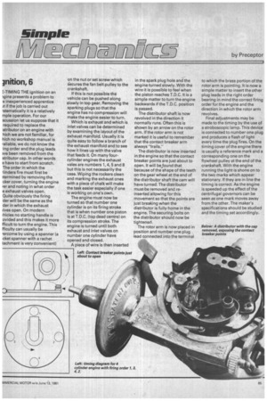
A piece of wire is then inserted in the spark plug hole and the engine turned slowly. With the wire it is possible to feel when the piston reaches T.D.C. It is a simple matter to turn the engine backwards if the T.D.C. position is passed.
The distributor shaft is now revolved in the direction it normally runs. Often this is shown by an arrow on the rotor arm. If the rotor arm is not marked it is useful to remember that the contact breaker arm always "trails."
The distributor is now inserted in the engine so that the contact breaker points are just about to open. It will be found that because of the shape of the teeth on the gearwheel at the end of the distributor shaft the cam will have turned. The distributor must be removed and reinserted allowing for this movement so that the points are just breaking when the distributor is fully home in the engine. The securing bolts on the distributor should now be tightened.
The rotor arm is now placed in position and number one plug lead connected into the terminal to which the brass portion of the rotor arm is pointing. It is now a simple matter to insert the other plug leads in the right order bearing in mind the correct firing order for the engine and the direction in which the rotor arm revolves.
Final adjustments may be made to the timing by the use of a stroboscopic lamp. This device is connected to number one plug and produces a flash of light every time the plug fires. On the timing cover of the engine there is usually a reference mark and a corresponding one on the flywheel pulley at the end of the crankshaft. With the engine running the light is shone on to the two marks which appear stationary. If they are in line the timing is correct. As the engine is speeded up the effect of the centrifugal governors can be seen as one mark moves away from the other. The maker's specifications should be studied and the timing set accordingly.