


An Aircraft Recovery Vehicle
Page 66
If you've noticed an error in this article please click here to report it so we can fix it.
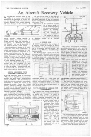
A DAMAGED aircraft lying in the 1-1, middle of a runway can seriously disorganize the operation of a busy airport and generally such obstructions are forcibly dragged away, often inflicting
still more damage to the aircraft. A special recovery vehicle capable of quickly lifting and taking away the largest aircraft, using the minimum of man-power, is disclosed in patent No. 792,685. (G. and R. Emanuel, 18 Via Tomasso Grossi, Turin, Italy.) Several designs are shown, all of which employ the same basic construction. A vehicle tows a gantry consisting of a pair of wheeled uprights (1) connected by an arched cross-member over the top. A pair of extending arms (2) is normally folded forwards on top of the longitudinals (3) but when required for use can be turned by power through 180' to form wheeled supports (4).
In use, the vehicle is backed up to the aircraft and the extensions are then swung out; they are of such height as to clear the wings. Normal lifting gear is incorporated and hydraulic power is used to move all the heavy parts.
SHOCK ABSORBER WITH UNIFORM ADJUSTMENT
SHOCK absorbers work by restricting the flow of liquid from one space to another, and quite often a unidirectional action is sufficient. But if restriction in both directions is required, it is practically impossible to adjust two valves to be identical in action. Patent No. 792,868 shows a scheme in which a single valve is made to do this and however it is adjusted, always operates equally in both directions. (Armstrong Patents Co., Ltd., Eastgate, Beverley, Yorks.) In the drawing. I and 2 are two liquidfilled cylinders, each containing a piston. When one or the other is moved, liquid is transferred to the other. In doing so it must unseat and pass through a conical valve (3). The area of the cone to the right of the seating is made equal to that of the left-hand large end, so that it is opened by th,..t. same pressure, whichever direction that comes from.
Adjustment of the restriction is given by a tapered plug (4) which can be screwed in of out as required and locked in position. Wherever this may be set, the equality of action is undisturbed. The scheme is said to be suitable for applying a damping action to a steering mechanism.
A HORSE BOX
A BODY designed for the carriage of fl horses forms the subject of patent No. 792,679. In the example illustrated, up to six animals may be carried. (G. Smith, Long Whatton, Loughborough. Lei cestershi re.) The drawing shows a plan view of the proposed body. The chief points are that the rear door (1) can be lowered to form a loading ramp and a side door (2) is 'similarly arranged. The. ceilinc and floor are provided with sockets for receiving
removable pillars (3). These .form the supports for partitions dividing the interior into separate stalls. To ensure adequate ventilation, duets in the roof pick up air from the front and lead it to the individual stalls.
NOVEL STARTING METHOD FOR TWO-STROKES
A SCHEME for starting two-stroke oil ra engines by fuel combustion is shown in patent No. 793,112. It refers to engines in which the air is supplied by a positive charging compressor and the basis of the invention is the using of this compressor as a rotary power unit to drive the engine. (Regie Nationale Des Usines Renault, 8/10 Avenue Emile Zola, Billancourt, Seine, France.) The drawing shows the layout including an air cleaner (1), an induction pipe and throttle (2) and the gear type charging pump (3). This in normal running feeds the engine with precompressed air as a supercharger.
The starting arrangements comprise a petrol injecting nozzle (4) and a sparking plug (5). All the driver has to do is to pull a starter knob; when this is done a petrol charge is injected and the plug sparks, firing the mixture and creating sufficient pressure. in the induction pipe to motor the compressor and so turn the engine.
The patent states that one firing is sufficient to turn the engine over a number of compressions, but should it fail to start first time, the operation can be repeated.
{
The patent also covers an automatic control f o r injection and ignition timing of the starting device.
IMPROVED ENGINE ACCESSIBILITY THE conventional radiator located at
the front of the vehicle is a major obstruction when attention has to be given to the engine, and patent No. 792,698 shows a novel layout in which two smaller radiators are used to replace the single one. (Daimler Benz A.G., Stuttgart-Unterturkheim, Germany.) The drawing shows the scheme applied to a 'six-cylindered lorry engine. The twin radiators (1) are disposed well to each side of the engine so that they form no obstruction. Each is fitted with its own fan, or a pressure blower may be used.
The drive to the blowers is by belt, triangulated from the engine pulley (2).