


From Drivers and Mechanics.
Page 22
Page 23
If you've noticed an error in this article please click here to report it so we can fix it.
TEN SHILLINGS WEEKLY is paid for the best communication received, and one penny a line of ten words for anything else published, with an allowance for photographs.
Workshop tips and smart re/'airs; long and successful runs; interesting photographs; all are suitable subjects. lye will knock your letters into shape and will prepare sketche,,, where necessary. before Publication. The absence of a sketch does not disqualify for a Prize. When To fling, use one side of the paper only and mention your employer's name as a guarantee of bona fides. Neither your on nor your employer's name will be disclosed. Payment Will he made immediately after publication. Address your letters to The Editor, THE COMMERCIAL MOTOR, 7-1.5, Rosebery Avenue, London, E.G.
Annual Bonuses are given to the most successful contributors.
THE ADDITIONAL DRIVERS PRIZE.
Extension of Time for Competitors.
In connection with the prize of two guineas which .we are offering to the driver who sends in the most complete and genuine list of replacements and repairs executed on a steam or petrol lorry of which he is in charge, during any definite period of 12 months, we must remind our readers that the last date for sending in letters is the first day of July, 1912.
'When Drilling Radial Holes.
The sender of the following communication has been awarded the 10s. prize this week.
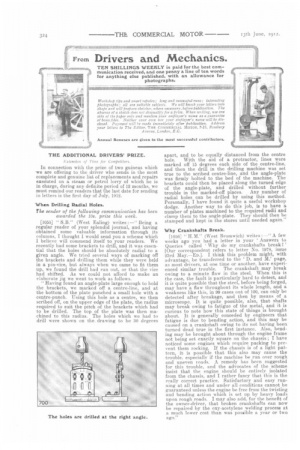
[1055] " S.B." (West Ealing) writes :—" Being a regular reader of your splendid journal, and having obtained some valuable information through its columns, I thought J. would send you a scheme which I believe will commend itself to your readers. We recently had some brackets to drill, and it was essential that the holes should be absolutely radial to a given angle. We tried several ways of marking off the brackets and drilling them while they were held in a pin-vice, but always when we came to fit them up, we found the drill had run out, or that the vice had shifted. As we could not afford to make an elaborate jig we went to work as follows. "Having found an angle-plate large enough to hold the brackets, we marked off a centre-line, and at the bottom of the plate punched a small hole with a .centre-punch. Using this hole as a, centre, we then scribed off, on the upper edge of the plate, the radius required to suit the pitch of the brackets which had to be drilled. The top of the plate was then machined to this radius. The holes which we had to drill were shown on the. drawing to be 30 degrees
apart, and to be equally distanced from the centre
hole. With the aid of a protractor, lines were marked off 15 degrees each side of the centre-line, and then the drill in the drilling machine was set true to the scribed centre-line, and the angle-plate was firmly bolted to the bed of the machine. The brackets could then be placed along the turned edge of the angle-plate, and drilled without further trouble in the marked-off places. Any number of radial holes can be drilled by using this method. Personally, I have found it quite a useful workshop dodge. Another way to do this job, is to have a number of plates machined to the required radii and clamp them to the angle-plate. They should then be stamped and kept in the stores until needed again."
Why Crankshaits Break.
[1056] "H.M." (West Bromwich) writes : —" A few weeks ago you had a letter in your Answers to Queries called Why do my crankshafts breakl ' [Our correspondent refers to letter No. 1978, issue 23rd May.—Eo.j. I think this problem might, with advantage, be transferred to the 'D. and M.' page, as most drivers, at one time or another, have experienced similar trouble. The crankshaft may break owing to a minute flaw in the steel. When this is the case, the fault is particularly hard to detect, and it is quite possible that the steel, before being forged, may have a flaw throughout its whole length, and a weakness like this, in 99 cases out of 100, can only be detected after breakage, and then by means of a microscope. It is quite possible, also, that shafts may break owing to fatigue of the metal, and it is curious to note how this state of things is brought about. It is generally conceded by engineers that fatigue is due to bending action, and this may be caused on a crankshaft owing to its not having been turned dead true in the first instance. Also, bending may be brought about through the engine frame not being set exactly square on the chassis ; I have noticed some engines which require packing to prevent them rocking. If the chassis is of a light pattern, it is possible that this also may cause the trouble, especially if the machine be run over rough and uneven roads. A remedy has been suggested for this trouble, and the advocates of the scheme insist that the engine should be entirely isolated from the chassis, and I rather fancy that this is the really correct practice. Satisfactory and easy running at all times and under all conditions cannot be guaranteed unless the engine be free from the twisting and bending action which is set up by heavy loads upon rough roads. I may also add, for the benefit of the owner-driver, that broken crankshafts can now be repaired by the oxy-acetylene welding process at a much lower cost than was possible a year or two ago." 'Cutting Keyways with a Jig.
L 1057] " L.D." (Slough) writes :—" I send you a sketch of a jig that I have made for cutting keyways in gear-wheels. This was a job which I was called upon to ,perform without the aid of a slotting machine, and, as I was anxious to save myself as much work as possible, I turned down a piece of round steel bar to the same diameter as the bore in the boss of the wheel. Then I had a slot, of equal width to the key which I was to use, cut down the whole length of the bar ; the depth of this slot was, roughly, half the diameter of the bar. The object of the slot was to serve as a guide for the cutting tool. The tool which is used for cutting the keyway when this method is used should be a nice sliding fit in the slot, and should, of course, be as long as occasion requires. A little packing may be placed at the bottom of the slot in the bar when the work of slotting the wheel boss is commenced. This packing should be of such thickness that the tool will take a nice and easy first cut 3 it can be thickened as other cuts are taken. When once the tool is made, a good heavy hammer is the only additional tool required to enable a good clean keyway to be cut in any wheel."
Copper Rod to Stop a Cylinder Leak.
L .1.05s3 " L. B." (Smethwick) writes :—"We had taken delivery of a new wagon for about six months, when one day I noticed a small leak of steam coming from the H.P. cylinder near the flange. Thinking that it was due to a small blow-hole in the casting, I took a centrepunch and gave the place one or two slight taps with a hammer with the intention of burring the leakage up. To my surprise a piece about 3-16 in. in diameter went right through, and I found it was where one of the stud-holes was drilled through into the. portway. The metal at that particular place in consequence was so thin that I could not tap it and fit a stud, so I had perforce to adopt another plan. I took out the stud which the makers had put in, and made up a longer one which would reach to within in. of the bottom of the hole. I then cut a piece of soft copper rod, the same diameter as the inside of the tapped hole, and about I in. in length. I dropped this to the bottom of the hole, and screwed the stud -tightly down. This made a fine steam-tight job. I then filed the copper which projected nearly flush with the cylinder, and hammered it over slightly."
Slitting and Springing.
[1059] " LB." (Srhethwick) writes:—" I am sending an account of one or two little repairs which I have carried out to the wagon under my charge. Some of the bearings have solid bushes, and it is not possible to adjust these in the ordinary way by putting in back liners when they are worn down a bit. The method I used may not be original or good form from an engineer's point of view, but it has answered the purpose. I have so far done two bushes, one on the Ill'. crosshead and the other in the frame bracket winch supports the crankshaft at the flywheel end. Both these bushes were worn oval, so I took them out and cut about in. out of the wall of the hushes with a hack saw. I then took a piece of sheet steel of suitable thickness and cut this to the proper size, that is the circumference of the bush, and bent it round, holding it in place by a piece of wire round the middle, and easing off the edge at one end by a file, to allow it to enter the journal. The wire was removed when the bush was partly driven. When it had been rammed home I tried the crankshaft M it, and scraped the high parts down until it was a good fit. The one at the fl.P. crosshead was done in similar fashion. Each of these bushes has now given four to six months service, and they are doing their work all right. It is rather a hard job to bend the steel round the bush, but it can be hammered roughly into circular form before the wire is wrapped round it."
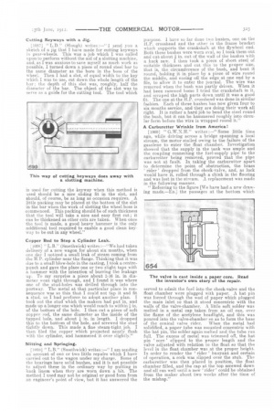
A Carburetter Wrinkle from America!
[1060] " G.W.N.H." writes :—" Some little time ago, while driving across a bridge spanning a local stream, the motor stalled owing to the failure of the gasolene to enter the float chamber. Investigation showed that the supply in the tank was ample and the coupling connecting the fuel-supply pipe to the carburetter being removed, proved that the pipe was not at fault. In taking the carburetter apart to determine the point of obstruction, the brass rider' dropped from the check-valve, and, as luck would have it, rolled through a chink in the flooring and was lost in the stream. A replacement was made in the following manner. "Referring to the figure [We have had a new drawing made.—En.] the passages at the bottom which served to admit the fuel into the check-valve and the float chamber were plugged with paper. A hat pin was forced through the wad of paper which plugged the main inlet so that it stood concentric with the walls of the valve-chamber. A little soft solder was melted in a metal cap taken from an oil can, over the flame of the acetylene headlight, and this was poured into the valve-chamber so as to form the base of the conical valve rider. When the metal had solidified, a paper tube was mounted concentric with the hat pin, the solder again melted and the tube run full. The excess of metal was trimmed off, the hat pin core ' clipped to the proper length and the valve adjusted with relation to the float so that the level in the float chamber was at the proper height. In order to render the rider ' buoyant and certain of operation, a cork was slipped over the stub. The carburetter was then placed in position, the float chamber filled, and the cap at the top screwed down and all ran well until a new 'rider' could be obtained from the maker about two weeks after the time of the mishap."