


A New Home-built Chassis.
Page 3
Page 4
Page 5
If you've noticed an error in this article please click here to report it so we can fix it.
The All British Car Company s Model for Bus or Lorry Work.
The bus chassis which The All British Car Company, Limited, of McPhail Street, Bridgeton, Glasgow, has just completed, and which that company is now testing, presents so many new and interesting features that it is proposed to deal with it here in a manner which its novel design demands. Simplicity, freedom from change-speed gears of the sliding or of the epicyclic types, economy of space, and an exceptionally low platform, are the predominating points in its design and construction. No other motorbus chassis in which the transmission is mechanical throughout, has ever met all these condi,tions so nearly as the one now under notice. The peculiar design permits the floor level to be as low as one foot ten inches from the underside of the floorboards to the ground level. The Police regulations are complied with in every respect, and, as there is a practically direct drive on all speeds, it should prove an extremely silent vehicle, provided the silent chains, made by Hans Renold, are kept reasonably clean and properly adjusted.
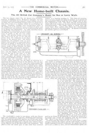
The overall length of the complete bus is 21 feet 6 inches ; the wheel-base is 13 feet ; and the height, from the ground level to the too of the roof, is 7 feet ii inches. The engine has four, horizontal cylinders, 51inches in diameter with a piston-stroke of 6 inches. The connecting rods are unusually long (20 inches), which, naturally, has the effect of reducing to a minimum the diagonal thrust on the pistons ; they are provided with an extra joint at the large end, which enables the crank-pin bearings to be removed and adjusted very easily. All the bearings are lubricated by a special device which automatically delivers an accurately-measured quantity of oil to the pistons and bearings : the effect of this should be perfect lubrication and an absence of smoky exhaust. Interchangeability of the mechanically-operated valves, and other parts, has also been given careful attention, in addition to easy access for renewals. The manner in which ball bearings of reasonable size are fitted is particularly smart, as may be seen in the line drawing of the crankshaft and its bearings which is reproduced on this page.
The crankshaft is made in two pieces, with two throws each, and mounted on single-row, Hoffmann ball bearings. The two parts are connected together, as will be seen in the illustration, by turning a male cone on one end of one half : this is ground and keyed into a female cone, which is bored in the adjacent end of the other half of the crankshaft. The joint is thus not called upon to take other than torsional strains, as a bearing envelops it. This form of construction is at once simple and cheap to produce, as it permits of the crankshaft's being made out of a forged slab of very hard, high-tensile steel. The shaft may be removed from either end of the crank-case, by reason of the large-diameter bearing-housings. The whole engine is slung from the frame from three points; this allows for a considerable amount of vertical or horizontal play. At normal revolutions per minute, 44b.h.p. is developed.
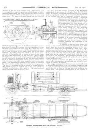
A massive flywheel is fitted, in which a multiple-disc, fric tion clutch is arranged : all the parts of these are well designed, and are completely enclosed in the oil-bath that is formed by the two parts of which the flywheel is built up_
The friction-plates are of large diameter, as may he seen in the drawing of tihe clutch-gear arrangement, and they
should, therefore, take up the load very easily and have a long life. As the sliding sleeve (A) is withdrawn, by means of the hanging levers (B) pressing on the face of the thrust washer (C) the plates are first relieved of the load due to the springs (1.); the two brake-disc faces (E and F) then come together, and the shaft (G) is retarded. The effect of this is that the plates are separated, and the outer ones are free to
rotate, whilst the inner plates are prevented from doing so by the driving-sleeve (H), which is keyed on to the shaft (G). The hanging levers (B) are operated by the clutch-pedal. The clutch-shaft (G) is continued beyond the brake-discs for a length sufficient to take the two chain sprockets (J and K), which, ride freely on the huh (L), and the two, claw clutches (M and N), which lock either J or K to the clutch-shaft. Two long feathers are fixed on the shaft (G); these permit the claw clutches (M and N) to transmit the drive from the clutch-shaft to
_[ either of the chain sprockets. For the pur_ —L pose of connecting together, the clawclutches (M and N), and to ensure that they move in correct relationship with each other, the clutch shaft is drilled out, and a plunger (0) is fitted ; this plunger connects the claw-clutches by means of cotters which pass through slots in the clutchshaft and allow the claw-clutches to be moved along its axis. It is not unlikely that some way of avoiding the necessity for these slots will be found by the makers_ The changing over, from one chain sprocket to another, or to or from neutral position as shown in the drawing, is effected by means of a foot-pedal and a bridle (P) engaging with the claw-clutch (M). M or N may then be meshed with J or K. It will be seen that there are only two gear-raCos, or gear changes, between the engine and the road wheels; with the engine running at' normal revolutions, the speeds thus given are 6 and 12 miles an hour, and all intermediate speeds are
obtained by the use of the throttle valve. The reverse gear i8 arranged in a separate gear-box, which forms an intermediate countershaft, and splits up into two chains of more reasonable length, what would otherwise be a very long chain drive. For both the forward speeds, the two claws on
the sliding pinion (0), seen in the Llustration of the reverse gear-box, are caused to engage with corresponding jaws on the hub which carries the gear ring (R); these two parts, consequently, revolve as one, or, all the three chain sprockets (5, T, and U) rotate at the same speed and in the same direction. In order to drive the vehicle in the reverse direction, the sliding pinion (0) is caused to move to the right, as seen in the illustration, by the fork (V). Moving Q to the right causes it to mesh with two pinions (W W) which, in turn, mesh with the pinions (X X). On the same spindles as X X, there are two more similar pinions, which mesh with the gear ring (R); this completes the reverse-gear train. The direction of rotation of each pinion is indicated by arrows on the outline face view of the reverse gear-box. The fork (V) is caused to slide by means of a earn quadrant (Y), which engages in a block (Z) on the same spindle as the fork and, therefore, slides with it. The cam quadrant (Y) is operated from the driver's seat.
The drive from the reverse gear-box to the differential countershaft is by means of a single; Hans Renold silent chain. A sectional view of the differential end of the countershaft is reproduced, and it will be seen that the shaft is not of the divided type, but is continued straight through, from one bearing to another. One of the differential bevel-wheels (a) is keyed to the countershaft ; the other bevel-wheel (6) is keyed to a sleeve (d),which rides loose upon the countershaft and has, keyed on its outer end, the off-side chain sprocket (e), and, in a mid-position, the off-side countershaft brake drum (f). The near-side chain sprocket and brake drum are, of course, keyed direct on to the opposite end of the countershaft (g). The countershaft, as are all other shafts where practicable, is mounted on Hoffman ball bearings, but in this case the bails are enclosed in a sleeve, working in a hollow, spherical housing, which will permit of a considerable amount of twist in the frame, without seriously affecting the alignment of the countershaft.
In addition to the two brake drums and bands on the countershaft which are operated by a footpedal, there are powerful expanding brakes in the rear wheel hubs; these latter are operated by a hand lever. Still, another powerful brake is at the driver's command, viz., the engine, which, by shifting the exhaust cams along the camshaft, can be converted into an air-brake. Both front and back axles are of high-grade nickel steel, with the wheels mounted on ball bearings. An illustration showing a section through a leading-wheel hub and axle-arm is given on the next page (363). Small grease lubricators are fitted to all pins, joints, radius rods, steering gear, spring links, and wherever lubrication by grease, is required.
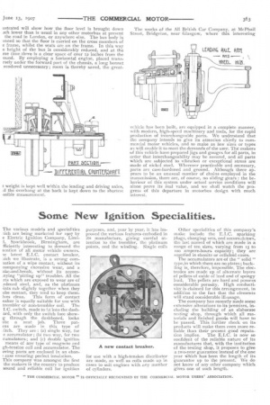
The unique arrangement of the chassis enables all parts of the engine and gearing to be got at easily without the use of a pit, and, what is more important, perhaps, for omnibus work, the well or floor of the bus body may be below the frame level. The general arrangement of the chassis as astrated will show how the floor level is brought down ach lower than is usual in any other motorbus at present the road in London, or anywhere else. The bus body is mned so that the floor is carried on the cross members of e frame, whilst the seats are on the frame. In this way
e height of the bus is considerably reduced, and at the me time there is a clear space of over 12 inches from the ound. rly employing a horizontal engine, placed transrsely under the forward part of the chassis, a long bonnet rendered unnecessary; room is thereby saved, the great
t weight is kept well within the leading and driving axles, ,d the overhang at the back is kept down to the shortest ssible measurement. vehicle has been built, are equipped in a complete manner, with modern, high-speed machinery and tools, for the rapid production of interchangeable parts. We understand that the company intends to give its attention chiefly to commercial motor vehicles, and to make as few sizes or types as will enable it to meet the demands of the user. The makers of this vehicle have prepared jigs and gauges for all parts, in order that interchangeability may he assured, and all parts which are subjected to vibration or exceptional stress are made of nickel steel. Wherever practicable and necessary, parts are case-hardened and ground. Although there appears to be an unusual number of chains employed in the transmission, there are, of course, no sliding gears : the behaviour of this system under actual service conditions will alone prove its real value, and we shall watch the progress of this departure in motorbus design with much interest.