


A Daimler-Benz Bus Design
Page 74
If you've noticed an error in this article please click here to report it so we can fix it.
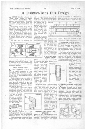
PIA CHASSIS intended primarily for bus work comes in patent No. 746,169 (Daimler-Benz A.G.,
Stuttgart Unterttirkheim, Germany). The patent deals mainly with the suspension arrangements at front and rear.
The engine is located at the rear of the vehicle. The front axle is a rigid member and utilizes a pair of helical springs (1) trapped between axle and frame. Fore-and-aft location is provided by a triangular radius-rod (2) universally pivoted on rubber bushes at point 3. Lateral location is given by a crosswise radius-rod (4) also rubberjointed.
The rear axle is attached via conventional leaf-springs (5) with the addition of a stabilizing rod (6). This is journalled on the frame members and its arms (7) are jointed one to each side of the axle assembly.
STEEL PISTON-RINGS
MANUFACTURING methods for the rapid production of steel piston-rings form the subject of patent No. 749,427 (Cross Manufacturing Co. (1938), Ltd., 33 Midford Road, Combe Down, Bath).
The drawing shows a cross-section of one type of ring. It is produced by rolling a red-hot steel wire into a helically grooved mandrel to give the external form (1). The roller used produces the form of the groove (2) and the tapering faces (3).
The mandrel is water-cooled and acts as a quench to give the necessary heattreatment to the wire. The coil so produced is slit axially, thus making a large number of rings. They are, of course, slightly helical, but this can be corrected if desired by a flattening operation. A prior complementary patent was No. 706.078.
A SELF-DISCHARGING BODY
AATERIALS as In diverse as cocoa, grain or coal can all be efficiently handled by a selfdischarging body shown in patent No. 749,203 (Charrold, Ltd., Tower House, 40 Trinity Square, London, E.C.3).
The drawing shows the general layout of the vehicle. The main part of the 1536 body is hopper-shaped and at the bottom is a long parallel channel along which runs a conveyor chain (1), driven by a geared motor (2). The bottom side of the conveyor is the operative portion, lying as it does along the floor. The con-. veyor feeds the material to a rear door (3) through which discharge takes place.
Loading is carried out through apertures (4) on the top. The aperture doors are hinged horizontally along line 5 and open upwards and outwards. In the case of a coal lorry, there may be separate compartments fitted with doors leadierg to the conveyor, so that different grades of coal can be carried and selectively discharged.
A SELF-HOLDING TAPPET SCREW THE adjustment of tappets usually calls for some skilful spanner-work, because often I h c lock-nut, when being tightened, has an annoying habit of altering the setting. Patent No. 749,310 shows a special screw requiring no locking, the threads being deformed so as to be permanently tigh t. (National Machine Products Co., 44225 Utica Road, Utica, Michigan, U.S.A.)
The drawing shows a typical example — an adjusting screw for an overhead valve. The rocker has a hole that is tapped in the ordinary way, but the screw is hollow and is split axially at three points as shown at 1. After splitting, the screw is expanded radially to a barrel shape, as shown somewhat exaggerated at 2. The expanded part acts as a spring, maintaining sufficient tightness to remain set, but not enough to resist a spanner. Its use reduces the weight of the rocker gear.
STARTING TWO-STROKE OIL ENGINES
DATENT N. 739.338 (Robert Bosch G.m.b.H., Stuttgart-W, Germany) discloses a novel method of starting a two-stroke oil engine. The starter
motor is reversible in action and is made to rock the crankshaft to and fro until it drives it over top dead centre. Means are provided for preventing the engine starting backwards.
A COMPACT ENGINE LAYOUT PATENT No. 746,399 (P. Morissette, 14558 Hartland Street, Van Nuys,, California, U.S.A.) discloses an improved engioe layout. The aim is to get the maximum power in the minimum space.
The engine is built up from units of three cylinders, one of which is shown in the drawing. The cylinders lie at an angle of 130° to ISO'. The valves of each outer cylinder lie on the upperside whilst the middle one has its valves disposed alternately right and left. This enables two camshafts to work the three sets. of valves.
The intake and exhaust passages are cast in a single manifold on each side; here again two units serve the three cylinders. The outer cylinder heads are alike but opposite, but the middle one is different because it has valves on both sides.
EXTREME-PRESSURE ADDITIVES (11LS for hypoid gears and similar ‘-of purposes are dealt with in patent No.. 749,835. which mentions certain chemicals said to impart pressure resistance. The oil used is of the phospho-sulphurized type. with the addition of a halogenated organic compound and a fatty or naphthenic acid or a metal salt thereof. The patent gives many typical formulae. (Esso Research and Engineering Co., Elizabeth. New Jersey, U.S.A.)