


MAGNETIC CLUTCHES.
Page 30
If you've noticed an error in this article please click here to report it so we can fix it.
A R4surne of Recently Published Patent Specifications.
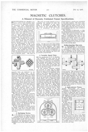
PECIFICATION No. 230,488, C. Q. 1,0 Payne, of New York, describes what appears to be an important invention in connection with electro-magnetic clutches. This class of clutch has been applied to gearboxes of motorcars, but although the change from gear to gear could be made by simply pressing a button, there were difficulties in manufacture that vast sums of money and years of expert experiments have not overcome. The left-hand view shows diagrammatically the construction of such clutches. One member has an annular groove formed in its face, into which a coil is fitted, which, when a current is passing through it, . forms the member into an electromagnet, so .that it attracts the other member of the clutch with such force as to cause adhesion sufficient to prevent independent rotary movement of the members forming the clutch. Such clutches have been employed for connecting a gear to a shaft, or for arresting movement in the mem
bers of epicyclic gears. The lines of magnetic force are indicated in our
illustration by dotted lines. An example of the application of such clutches was to be seen in the Elma gear which attracted a good deal of attention some years ago. The main difficulties which experimenters were met with in this class of gears lay in the selectiOn of the iron or steel which formed the magnet and the pole piece ; if the metal were too soft it would tear up as the lubricant was gradually squeezed out from between the surfaces, whilst, on the other hand, if the steel were of a hard nature it would not lose its magnetism quickly enough to enable changes to be made from one gear to another. •
The inventor claims to have overcome these difficulties by forming grooves in the faces of the magnet and pole pieces, which, he claims, will increase the magnetic effect, as by forming such grooves each intersection crosses another and four corners are formed, at the apices cf which a great accumulation of magnetic density occurs, as illustrated by the shading in the right-hand view.
By the employment of these grooves he claims to be able to face both members with a thin layer of harder metal, such as manganese or chromium, to resist wear.
A Springing Device.
R J. H. SUZAN, of Asnieres, France,
in specification No. 245,112, shows a well-known form of spring construction as applied to the front of a motorcar, but with certain new points. Unfortunately, the specification does not enlighten us as to the object aimed at.
B46 The point of novelty appears to be in arranging the springs so that the point of attachment of the upper spring to the frame is farther from the centre of the chassis than the point of attachment of the lower spring. By this means the upper spring describes a different curve to that of the lower one when deflected. The result of this is that the slight angle at which the wheel lies with the perpendicular is reduced as the spring is deflected, so that when fully deflected the wheel will be actually perpendicular.
A Variable Speed Gear.
IN the specification of F. C. Hatcher, No. 252,830, we meet with an old friend in a somewhat new form. Usually, the efforts of inventors in connection with variable speed gears have been in the direction of providing a gear that will run direct when on top gear, its internal mechanism being at work only when on the lower gears.
In this instance, however, matters are reversed, as what may be called the lowest gear is direct, whilst all other ratios are obtained by imparting extra speed to the driven shaft by means of free-wheel clutches. The inventor says that he does not confine himself to the use of the particular type of free-wheel clutch shown, and we think he would be well advised to abandon it. The driving and driven shafts are co-axial, as in an ordinary gearbox, the one shown in section being the driven. The driving shaft carries with it a flange from which project three pins on which the three clutches are free to revolve. Each of the inner members of the free wheels is urovided with a pin, which is shown hi section.. The pins nrdject into an annular groove in an eccentric, so that the clutches oscillate in their path round the central shaft. This oscillation of the inner part of the
clutch imparts a step-by-step movement to the outer member. The latter, having teeth formed at its outer edge, which engage with the pinion formed on the driven shaft, urge the latter forward at an accelerated speed at. each oscillation of the clutches.
The eccentric is adjustable, so that any desired degree of eccentricity, within certain limits, can be imparted to it.
When the ring is set truly with the shaft no oscillation takes place in the clutches, consequently the speed of the driving and driven shafts are equal. \Them however, the ring is eccentric to the shafts to its fullest extent, the driven shaft is revolving at its fastest in relation to the driving shaft.
Roller-bearing Big-ends. w A. MITCHELL, in specification No. 252,762, shows a construction of crankshaft in which •roller bearings can be employed, as the crank can be made of steel that can be case-hardened and ground so as to form the inner ring
of the bearing. The specification refers particularly to the use of that class of roller bearing in which a chain forms she cage that separates the rollers. We see no reason, however, why this particular kind of bearing need be used: Cotter pins are shown as being used to prevent the component parts from twisting in their conical fittings. The fitting of such pins to parts which haye been hardened and ground is, however, not an easy matter.
A Split-skirted Piston.
JOHN WILLIAMS and Judson Williams, of Philadelphia, U.S.A., in specification No. 244,43:3, show a form of piston in which the skirt is split at . two places—the splits being situated at right angles to the axis of the gudgeon pin. The head is partly separated from the skirt by splits, as shown, which run parallel with the rings.
So far, there is no novelty in the construction ; the claim, however, concerns the fact that the skirt is formed as shown, slightly tapering and largest at the bottom. If the prevention of piston slap is the object , of the invention, we hardly Think that , this form of piston will prevent it, as it is well understand here that to prevent slap a.piston must be elastic as nearly as possible along its whole length, and not at one end only.