


MODERN GARAGE DESIGN.
Page 28
If you've noticed an error in this article please click here to report it so we can fix it.
A 'Résumé of Recently Published Patents.
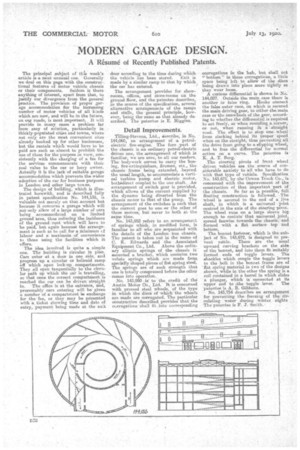
The principal subject of this week's article is a most unusual one. Generally we deal on this page with the construe-. tional features of motor vehicle chassis or their components. Seldom is there anything of interest, apart from that, to justify our divergence from the general practice. The provision of proper garage accommodation for the increasing n-urnber of inviter vehicles of all kinds which are now, and will be in the future, on mer roads, is most important. It will provide in many cases a problem far from easy of solution, particularly in thickly-populated cities and towns, where not only are the most convenient sites already booked up for other businesses, but the rentals which• would have to be paid are such as almost to prohibit the use of them far the purpose in view, consistently with the charging of a fee for the services commensurate with their real value to the car or lorry owner. Actually it is the lack of suitable garage accommodation which prevents the wider adoption of the car for business purposes in London and other large townie The design of building, which is illustrated herewith, and is described full, in patent 'specification No. 144,135, is valuable not merely on thet account but because it concerns a garage which will notanly allow of a large number of oars being accommodated on 'a limited ground area, thus reducing the incidence of the ground •rent which will have to be paid, but again because the arrangement is such as to call for a minimum ef labour and a; maximum of convenience to those using the facilities which it offers.
The idea involved is quite a simple one. The building is circular in plan. Cars enter at a door in one side, and progress up a circular or helicoicl ramp off which .open lock-up compartments. They all open tangentially to the circular path up which the car is travelling, so that once the correct compartment is reached the car can he driven straight in. The office is at the entrance, and, presumably cars entering will be given a number of a compartment iii exchange for the-fee, or they may be presented with 'a. ticket showing time and date of entry, payment being made at the exit
door according to the time dieing which
the vehicle has been stored. Exit is made by a similar ramp to that by which the car has entered.
The arrangement provides for showrooms, offices, and stare-rooms en the ground floor, and the patentee describes, in the course of the specification, several alternative arrangements of the ramps and stalls, the general principle, however, being the same as that already de, scribed.. The patentee is E. Higgins.
Detail Improvements.
Tilling-Stevens, Ltd., aleseribe, in No. 144,060, an arrangement of a petrolelectric fire-engine. The fore part of the chassis is an ordinary petrol-electric driven one, the arrangement of which is familiar, we are sure,-to all our readers. The bodywork serves to carry the hosing, fire-extinguishers, firemen, etc., the chassis frame being extended, beyond the usual length, to accommodate a vertical turbine pump and electric motor, bothielirect coupled to the one shaft. An arrangement of switch gear is provided, which allows of the current supplied be the dynamo being diverted from the chassis motor to that of the pump. The arrangement of the switches is such that the current goes to one ,,er the other of these motors, but never to both at the same time.
No. 143,952 refers to an arrangement of springs whichin modified form, is familiar to all who are acquainted with the details of the London bus chassis. The patent is taken out in the name of C. K. Edwards and the Associated Equipment Co., Ltd. Above the ordinary elliptic springs of the chassis is' mounted a bracket, which contains two volute springs which are made from specially shaped pieces of flat spring steel. The springs are of such strength that one is totally compressed before the other comes into operation..
No. 193,950 is to the credit Of the
Austin Motor Co. Ltd. It is concerned with pressed steel wheels, of the type in which the discs of -which the wheels are made are corrugated. The particular construction described provides that the ce rrugations shall fit into corresponding
corrugations in the hub, but shall not €' bottom" in those corrugations, a little space being left to allow of the discs being drawn into plate more tightly as they wear loose. ' A carious differential is shown in No. 194,027. Outside the main case there is another Or false ring. Hooks connect -the false outer case, on which is secured the main driving gear, to either the main case or the aline/Beds of the gear, according to whether the differential is requited to act freely, as when rounding a. corner; or not, when running in astraight road. The effect is to stop one wheel • from slacking behind its proper speed when on the straight, thus preventing all the drive from going to a slipping wheel, and to free the differential for normal action an a, curve. The patentee ia K, A. T. Berg. The steering pivots of front wheel driven vehicles are the source of considerable anxiety to all who have to do with that type of vehicle. Specification No. 143,671; by the 'CowanTruck Co., is concerned with the improvement of the construction of that important 'part of
the chassis. So far as is possible, full' floating. construction is followed. • The wheel is secured to the end of a live shaft, in which is a universal jcint centred in the axis of the steering pivot. The wheel rune on a large sleeve big enough to contain that universal joint, spread fanwise towards the chassis, and formed with a flat surface top and bottom.
The bonnet fastener, which is the subject of No. 143,672, is designed to prevent rattle. There are the usual upward curving brackets on the side of the bonnet, and into them fit suitably formed ends of toggle levers. The shackles which couple the toggle levers to the bolt in the bonnet frame are of 'flat spring material in two of the designs shown, while in the other the spring is a. coil contained in a barrel in which slides a plunger, which is' connected at its upper end to elle toggle lever. The patentee is A. B. Gibbons. No. 193,754 describes an arrangement for preventing the freeziee of the circulating water during winter nights The' patentee is F. J. Smith..