


Patents Completed.
Page 24
If you've noticed an error in this article please click here to report it so we can fix it.
Armstrong-Whitworth Piston Construction. Bullock Traction Engine.
Fowler Driving Gear for Agrimotors. Robey Winding Drum.
Copies of complete specifications of the patents published on this page can be obtained from the Sales Branch,. Patent Office, Holborn, W.C., at the cost of sixpence for each specification.,
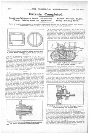
SIR W. G. ARMSTRONG, WHITWORTH AND CO., LTD., and L. J. LE MESURIER., No. 16,453, dated 22nd November, 1915.—The accompanying drawings show an improved form of guard which is fitted inside the piston of an internalcombustion engine to prevent the 'splashing of oil up on to the piston. A groove is formed around the interior of the piston and two segmental plates are inserted into it opposite one another. A third plate with straight sides and curved ends is then sprung into the groove between the segmental plates and it. locks them all in position. The three plates may be spot-welded together if desired.
R. IL FOWLER AND N. WEBSTER, No. 10,414, dated 17th July, 1915.—This invention is applied to agricultural machines generally, of the type in which two driving wheels are each driven through a ratchet clutch, which gives a drive only in the forward direction. Means are usually provided in these machines for wholly disengaging either of the clutches when necessary, as, for example, when turning a sharp corner. No provision has been made, however, for reverse drive, and according to this invention means are provided for locking the driven member of the clutch, to the driving shaft 60 that it will rotate in both directions with it.
Various constructions are described and illustrated in the specifications, and the simplest is reproduced in the accompanying drawing. The driven member of the clutch is integral with a driving pinion, and it is mounted loosely upon the driving shaft. A cap-plate is secured on the driven, member, and one or more holes or slots are formed in it to register with similar holes in the driving shaft, so that by inserting a pin or pins the two can be positively locked together to give a drive in either direction. F. B. DERN (BULLOCK Tnacron Co.), No. 15,388, dated 1st November, 1915.— The accompanying drawing shows a side view of a triction engine of the double endless-track type, in which steering is effected by varying the relative speeds of the two tracks. Each track is driven separately through a friction clutch shown at the top of the vehicle near the engine.
These clutches are controlled by levers which extend towards the rear, and have handles beside the driver's seat, there being one lever controlling each track. The transmission gearing also includes a brake for each track. These brakes are separately controlled by cranked arms, one of which is shown under the fuel tank at the rear end of the vehicle.
These arms are so that as to be engaged by the clutch. i controlling levers n such a manner at when• the lever is moved to 'declutch the brake is applied.
W. T. 11Er.r. and L. W. JONES, No. 16,757, dated 27th No. vember,.1915.—This invention relates to motor vehicles of the type in which a winding drum is carried by the driving axle, and can be locked to it when it is required to be operated. The accompanying drawing shows one road wheel and a part of the driving axle on which the winding drum is mounted. The driving shaft drives the road wheels through pins. The winding drum is freely mounted on a bearing which is itself on a square on the driving shaft. A suitable clutcdr device can lock the drum to the bearing. When the drum is to be used, the road wheels are chocked and the driving pins of one of•the wheels are withdrawn BO as to leave the shaft free." The winding drum is then clutched to it and the transmission gear driven by the engine. Four gear ratios are available, by using the two speeds of the transmission gear and also the two speeds obtained by using the diffenenfial as an epicycle driving gear.