


Equalizing the Load on Bogie Axles
Page 68
If you've noticed an error in this article please click here to report it so we can fix it.
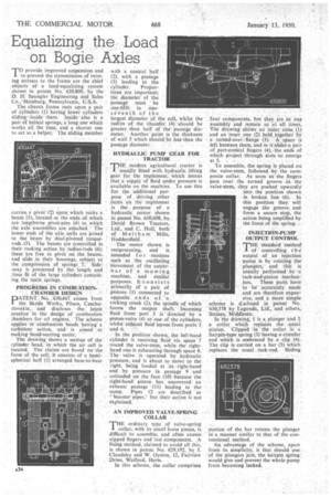
TOprovide improved suspension and to prevent the transmission of twisting stresses to the frame are the chief objects of a load-equalizing system shown in patent No. 630,800, by the D. H. Spangler Engineering and Sales Co.,, Hamburg, Pennsylvania, U.S.A.
The chassis frame rests upon a pair of cylinders (1) having lower cylinders sliding inside them. Inside also is a pair of helical springs, a long one which works all the time, and a shorter one to act as a helper. The sliding member
carries, a pivot -(2) upon:. which reicks a beam. (3), located., at the ends of_which are lengthwise pivot-pins 0) to which the axle assemblies are attached. The lower ends of the aide units are joined to the beam by diial-pivoted tOrquerods (5). The beams are controlled in their rocking action by' radius-rods (6); these are free to pivot on, the beams, and slide in their housings, subject to the compression of springs 7., Side ;way is prevented by the length and close fit of the large cylinders contain
ing the main springs.
PROGRESSS IN COMBUSTIONCHAMBER DESIGN ;
PATENT No. .630,447 comes from the Skoda Works, Pilsen, Czechoslovakia, and discloses the ateat practice in the design of combustion chambers for oil engines. The scheme applies to combustion heads havinga turbulent action, and is aimed at making hand-starting easier.
The drawing shows a section of the• cylinder head, in which the air cell is located. The claims are based on the form of the cell; it consists of a hemispherical half (1) arranged base-to-base
with a conical half ' (2), with a passage (3) leading to the
cylinder. Proportions are important; the diameter of the pa§sage must be one-fifth to oneseventh of the
largest diameter of the cell, whilst the radius of the chamfer (4) should be
greater than half of the passage diameter. Another, point is the thickness of wall 5 which should be less than the
passage diameter. .
HYDRAULIC PUMP GEAR FOR TRACTOR 71"HE modern agricultural tractor is I usually fitted' with hydraulic lifting gear for the implement, which means that 'a supply of fluid tinder pressure is available on the machine. To use this for the additional pur pose of driving other .itenris on the implement is the purpose of a hydraulic motor shown in patent No. 630,608, by David Brown Tractors, Ltd., and C. Hull, both of Melt ha rn Mills, Huddersfield
The motor shown is reciprocating, and is intended 10 r --motions such as the oscillating movement of the cutterbar of a mowing machine, and similar purposes. It consists primarily of a pair of .pistons (1) connected to opposite ends °f .:.a. rocking crank (2), the spindle of which forms the output shaft. Incoming fluid from • port 3 isdirected by a piston-valve (4) to one of the cylinders, whilst exhaust fluid leaves from ports '5
and6. ." •
In the position' shown, the left,hancl cylinder is receiving fluid Via space 7 round the valve-Stem, while the righthand oneis exhausting -through space 8. The valve is operated by -hydraulic pressure, and is about. to move to the. right, being loaded at its:, right-hand end by pressure in passage 9 and unloaded on the 'face (10)because the right-handpiston has uncovered an exhaust passage '(I1) -leading to the :sump. Pipes 12 are described as " &roster pipes," but their action is not explained.
AN IMPROVED VALVE-SPRING COLLAR THE ordinary type of valve-spring collar, with its small loose pieces, is difficult to assemble, and often causes nipped fingers and lost components. A fixing method, claimed to avoid all this, is shown in patent No. 629,192, by J. Cloudsley and W. Oyston, 12, Fairview Drive, 'Watford, Herts.
In this scheme, the collar comprises
four components, but they are in Ong assembly and remain so at all times. The drawing shoWs an outer cone (1) and an inner one (2) held together by a turned-over flange (3). A space is left between them, and in it'slides a pair of part-conical fingers (4), the ends of which project through slots to emerge at 5.
To assemble, the spring is placed on the valve-stem, followed by the composite collar. As soon as the fingers pass over the turned groove in the valve-stem, they are pushed upwardly
into the position shown in broken line (6).. In this position they. will engage the groove and form a secure stop, the action being amplified by the force of the spring..
INJECTION-PUMP OUTPUT CONTROL
-THE'standard method' I 'of controlling t h e output' of an injection pump is by rotating the' plungers, and this is usually performed by -a rack-and-pinion mechanism. These parts have to be accurately made and are therefore expensive, and a more simple scheme is d:sclosed in patent No. 630,318 by Lagomla, Ltd., and others, Staines, Middlesex.
In the drawing, 1 is a plunger and-. a collar which replaces the usual pinion. Clipped in the collar is a hairpin-type spring (3) having a circular end which is embraced by a clip (4). The clip is 'carried on a bar (5) which replaces the usual rack-rod. Sliding
motion of the bar rotates the plunger in a manner similar to that of the conventional method.
An advantage of the scheme, apart from its simplicity, is that. should one of the plungers jam, the hairpin spring. would give and prevent the whole pump from becoming locked.