


Loading Hoist for Refuse Vehicles
Page 58
If you've noticed an error in this article please click here to report it so we can fix it.
THE usual method of collecting refuse on a house-to-house basis is to empty the bins direct into the vehicle. When dealing with large blocks of flats however, this method is not practicable, and the procedure is to empty the bins
first into a larger container, and to take this to the vehicle for the final tipping. Patent No. 682,876, shows a hoist for dealing with these containers, which are too heavy to be manually tipped. The patentees are C. Edwards and SheIvoke and Drewery, Ltd., Letchworth, Herts.
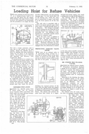
The proposed device is a simple structure which can be quickly fitted to any vehicle to deal with current needs. The drawing shows an end view with the hoist in position as shown at I. Two pairs of channel members are used, one pair (2) being straight, and the other (3) curved. A roller-bearing carriage runs inside the channels, and the wheeled container (4) is hooked thereto. When raised by winch and cable, the container first rises vertically and then tips into the position shown at 5. It is advisable that the body should be supported from the ground when the hoist is being used, and special quick-acting jacks are provided. ,They consist , of snaii-cams which can be turned until they touch the ground.
POWERED TWIN AXLES
PATENT No. 684,548 comes from Eaton Axles. Ltd., 25, Victoria Street, London, S.W.1, and deals with bogie axles and their driving arrangements. The chief novelty is that one of the axles has a two-speed drive, but the other has not. If one axle be put in low gear, whilst the other is in its fixed top gear, the torque is, nevertheless, evenly distributed by a differential gear between the two axles.
Referring to the drawing, the drive to the leading axle arrives via the propeller-shaft (1) and is transmitted to a bevel-planet carrier (2) engaging gears one on each side of it. This divides A40 thellrive differentially, one part passing through gear 3 to the bevel drive (4) of the leading axle, whilst the other part is transmitted via gear 5 and shaft 6 to the bevel pinion (7) of the rear axle.
The rear axle is provided with a built-in two-speed epicyclic gear which gives either a straight-through drive or a reduction. The change is brought about by sliding the sun-wheel (8) in an endwise direction by means of a forkand-collar (9). The shifting is performed by a reversible electric motor (10) and its reduction gear.
When the same ratio is applied to both axles, the input differential is Locked by a sliding dog (11) which couples one of the gears to the input
shaft. Electrical interlocks are provided to prevent the second speed being engaged when the differential is locked.
PROTECTING EXHAUST VALVE STEMS THE stem Of an exhaust valve is I continually being covered by a thin film of carbon which, as the valve closes, is carried into the guide. This sets up an abrasive action which erodes the bore of the guide. A scheme for shielding the exposed portion of the stem from the gases forms the subject of patent No. 682,448 (Societe D'Etudes de Machines Thermiques, 7 rue Auber, Paris). The scheme also protects the stem from heat which, in a super charged four-stroke engine, may reach a temperature as high as 600 degrees C.
The drawing shows the proposed attachment fitted to an overhead exhaust-valve. The guide is arranged to receive a screwed-in sleeve (I) which encloses the valve-stem to a point as close to the head as possible.
The sleeve has internal air-spaces (2) which impede the transmission of heat to the stem, direct metallic conduction :being possible only through very thin walls. The patent shows a second scheme in which an inserted valve-seat is made integral with the heat screen, the two parts being interconnected by edge-on fins.
OIL ENGINE HAS CO-AXIAL VALVES.
PATENT No. 684,635, from A. Buchi, Winterthur, Switzerland, discloses a design for an oil engine in which the valves are co-axial, one sliding inside the other. The patent is specifically concerned with the shape of the combustion chamber used in conjunction therewith.
Referring to the drawing, the chamber is located mainly in the piston crown, and is rather shallow with res, pect to its diameter. The valve arrangements comprise an outer annular valve (I) seating at 2 in the cylinder head; this is the inlet, and its air-supply passage (3) is of spiral outline so as to impart a swirl to the incoming charge:
The exhaust valve (4) works inside the inlet. its passages running throngh the large stem. When the exhaust valve is opened, it descends to the broken-line position (5) leaving very little space between it and the piston. This minimizes the chance of creating pockets of burnt gases, and thus ensures excellent scavenging.
Two injectors (6') are provided; these are set at a tangent to the combustion space and inject in a downstream direction. The patent shows also the scheme modified to suit a four-cycle petrol unit and a two-stroke oil engine.