Adapting the Moving-floor Principle for Unloading Root Crops
Page 40

If you've noticed an error in this article please click here to report it so we can fix it.
THOSE engaged in the transport ol sugar beet will be interested in a device shown in patent No. 527,916 from Miag Muhlenbau und Industries A.G., Germany. The patent describes a special unloading mechanism for dealing with this crop.
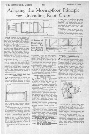
Before loading, there is laid in the bottom of the body a number of round cross-bars (1) connected by chains at the ends. The first chain (4) is the same length as the crossbar spacing, but the others. (5) are in excess of this, and are slackly laid on the floor. At the front of the body is an angle-section barrier, to which the front pair of the chains is secured.
To unload, the tailboard is lowered to form a ramp, and the chain (2) is hauled. The load is thus discharged in a spread-over manner as the various chains take up the slack, thebarrier being the last unit to be hauled rear wards. The _factory conveyor (3) is thus enabled to deal with the load in a uniform manner._ DECLINKERING DEVICE FOR GAS • PRODUCERS
A N invention claimed to double the normal running distance of a producer-gas vehicle is disclosed in patent No.527,775, which comes from A. Fitton
and T. Hurley, Fuel Research Station, River Way, Blackwall Lane, London, S.E.10.
The improvement is in the construc-` tion of the bottom of the fire zone, and is applicable to producers of the crossdraught type. The drawing shows the lower part of the_body and the ash-pan. A plate (1) upon which the fuel rests is positioned between upper and lower guides (5 and 4), so that it can be pulled out like a drawer when the door (2) is removed. The lower guide (4) is cut away at intervals to font a number of spaces (3).
In operation, during the first part of B34
the journey, clinker and ash gradually. collect on the plate (1) until the gas supply begins to fall off. When this occurs, the door (2) is opened and the plate (1) pulled out by a hooked tool. The clinker then falls into the ash-pan through the spaces (3). The door is replaced, and the journey resumed without the plate (1) being reinserted.
The removal of the plate allows some of the fuel to fall as well as the waste product, and this gives a fresh impetus to the combustion, to whichthe extra length of run is probably due.
LIGHTWEIGHT CONSTRUCTION IN TIPPING BODY
ATIPPING body, constructed almost entirely from sheet metal, is shown in patent No. 527,527 by Fisher and Ludlow, Ltd., and J. Percival, Albion Works, Rea Street, Birmingham. The drawing shows the body ready for pivotal mounting upon the vehicle chassis.
The main longitudinal girders (5) are 'bent from sheet metal and are of channel section, open side uppermost. End pieces (6) are welded in, and similar pieces are spaced. along the length at intervals. Resting upon the long' girders are transverse bearers (3): these are also formed from sheet, and are of channel section. These crossmembers carry the floor, which can be all metal or metal-faced wood, the securing method being welding or bolting.
The sides consist -of channel-section chock-rails (2) to which the drop sides are hinged, whilst each corner is given an upstanding pillar, also of channel section, to carry the non-pivoting panels. All the side panels are folded at their edges for stiffening, and may he further reinforced by X-shaped pressings. The hinge pieces (1) are welded on, each forming a box section. The weight is taken on feet (4), one. pair of which forms the pivot mounting.
A feature is that the body Is inexpensive to manufacture, principally because all the sheet-metal parts can be formed by simple folding machinery, no expensive press-tools being required.
DOUBLE-PURPOSE HYDRAULICBRAKE IMPROVEMENT
SELF-SEALING washers of the usual type function effectively when under pressure, but are liable to leak slightly when-not-loaded. To prevent this leakage when _hydraulic brakes are in the " off " position is the object of a scheme shoWn in patent No. 527,773 by Bendix Ltd., and G, Roberts, both of King's Road, Tyseley, Birmingham.
The drawing shows the operating cylinder of an hydraulic brake mechanism in which the shoes are expanded by a wedge-like member (5) when moved to the left. The wedge i3 formed on the end of an hydraulic plunger which is sealed when in use by
a flexible ring (1) which has a selfsealing action under pressure. To prevent leaks when not in use, the end of the plunger is recessed to form an annular step which, when out of action, is pressed against a sealing washer (4) located in the end wall of the cylinder, adjacent to the fluid supply (2).
A further advantage is. that the plunger also acts as a two-diameter piston until the step is clear of the boss (3), -and by selecting suitable proportions, the early drum-contacting motion may be made to occur at a higher speed.


