


An All-mechanical Servo Brake
Page 66
If you've noticed an error in this article please click here to report it so we can fix it.
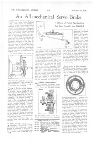
FROM Bendix Aviation Corporation, 105, West Adam Street, Chicago, U.S.A., comes patent No. 437,620, in which: is shown a servo-brake system operated by the kinetic energy of the vehicle. Behind the gearbol: is mounted apair of semi-stationary discs (4 and 5) between which revol‘es a thi?-1 disc faced with friction fabric. The basis of the patent is the method ot operation by means of the rocking bar (:1). to one end of which is connected the pedal rod (0), whilst the other com
prises the hand lever link (1). In operation, movement of the pedal or hand lever, or troths compresses the discs and tends to turn the two outer members. These pull on an arm (2) carried by the cross-shaft. In order to provide for reverse running a similar arm (not shown) • is connected to th..• opposite side.
The patent describes this systn as
being specially applicable to tractortrailer :assemblies, whilst manufacturing advantages are claimed owing to its suitability for presswork.
Easing the Starting of Oil Engines.
THE problemof starting high-compression vehicle engines is dealt with in patent No, 437,703, in which some further suggestions are put forward by Robert Bosch A.G., Stuttgart, Germany. The , method consists of temporarily increasing the closing force of the spring-loaded injection nozzles to approximately twice the normal running amount. Furthermore, the pump is adjusted to inject considerably more than the full-load quantity of fuel, and the moment of injection is slightly advanced. , All these conditions, it should be understood. obtain only during the duration of the starting operation ; once the engine has started, normal conditions automatically return. :
The patent describes fully the methods used, both mechanical and electrical.
An Easily Fitted Servo-brake Control. A BRAKING arrangement especially
suitable for commercial vehicles subject to overload is described by Hamilton Motors (London), Ltd., and W. D. Theed, both of 466-490, Edg • ware Road, London, W.2, in patent No. 437,610. The advantages of the scheme are easy adaptation to existing vehicles, progressive application of the power, and the absence . of interference with the manual system.
The accompanying drawing shows the pedal rdds and control valve, the vacuum cylinder (not shown) being connected to a crank on the cross :shaft (7). Operation of the pedal applies the brakes manually, until such time -.as the adjustable projection "(6) makes contact with the valve pis ton (5). After this point has been passed, a progressive suction is applied by the tapering valve (4) from the intake line (3) to the vacuum cylinder pipe (1.). Release of the power braking occurs when the atmospheric ports (2) are uncovered by the piston.
A Simple Centrifugal Clutch.
THE automatic centrifugal e.14citt seems to be gaining in popularity, and in Patent No. 436,016 is shown
new and simple design by Parry, Plough Inn, Eathorpe, near Learning
ton, and C. L. Robinson, Burnthurs, Princethorpe, near Rugby. In the drawing, which shows a section, the engine flywheel carries an inserted steel plate -(2). Across the face of this plate is cut a number of :grooves (1), their depth decreasing as the diameter increases. In each groove a steelball is placed, and in operation the centrifugal action causes them to move outwardly and in so doing pressplate 3 in a direction to compress the friction rings. Although the drawing shows the plates (2 and 3) as being similar, the latter is saucer-shaped and has no grooves across its face.
Improvements in Brake Assembly.
FROM the Budd Wheel Co., 2,500, Hunting Park Avenue, Philadelphia, U.S.A., 'comes Patent No. 435,221, in which is described a new design of
brake-drum assembly. Dealing with
the general layout first, the shoes are expanded by two cams (one on each side) carrying extending -levers (1). These levers are coupled by links to an operating yoke (4), which is moved in a vertical direction by externally connected lever 3.
The patent lies in the means for ensuring the application of equal forces to the two shoes. Without special precautions a higher pressure Would be applied to the upper shoe, owing to the floating cam fulcrumming on its inner corner and applying the load from the outer edge; on the lower shoe the converse would apply.. To prevent this disparity. it is proposed to provide two notches (2) in each lever, and place the yoke links in .either the inner ot outer one as required: -Thus,-in the example shown,, with the rotation as indicated by the arrow, left-hand lever 1,1-tas its link farther from the centre than has the right-hand one.