


Keys and Cotters.
Page 5
Page 6
If you've noticed an error in this article please click here to report it so we can fix it.
Contributed by an Engineer-in-Charge.
Taking into consideration the important part that keys play in all classes of machinery, it is of the utmost importance, especially in steam wagons or tractors, that they should be a good fit, otherwise endless trouble will result. Keys not only have to withstand the ordinary stresses set up by the moving portions of the transmission which they hold in place, but, at times, probably when starting on a hill after changing gear, or when starting a vehicle out of soft places, they are often taxed to their utmost; that is the time that any weakness reveals itself. A loose key, or cotter, should have immediate attention, because, unless this is done, a serious accident may occur. Bad fitting is,
probably, the cause of more keys working. loose than an
else, although a shaft that is slack in the boss of a wheel, no matter how good the lit of the key is, will only last a short time before it becomes slack. Generally speaking, when this is the case, a " liner," sometimes made from tin, is inserted, and the key flogged home again ; there the matter ends until the key has thumped the keyways a little bigger, when a thicker liner is inserted.
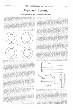
Figure i shows the three usual forms of key which are commonly used :—A saddle key (A) is rounded on the bottom to the same radius as the shaft, and a keyway is cut in the boss of the wheel; B is a key of another form, a flat being filed, or machined, on the shaft and the key left flat on the bottom ; C is a sunk key, part of it being let into a keyway machined in the shaft. The saddle key (A) is a type of key now very seldom used, as its holding power is small. The flat key (B) has considerably more holding power than the saddle key, and for parts not subject to very severe strains answers remarkably well. The key (C) is the safest and most secure of all types, and the one commonly employed; for shafts which have to carry exceptionally severe strains, two sunk keys are fitted, as shown on D, close together instead of opposite one another, the object being to prevent the keys pulling the boss oval. The key shown in Fig. 2 is known as a " gib head" and is usually employed when it is impossible to get at the smaller end of a key to drive it out when necessary. In Fig. 2, the sides of the key (A) are parallel to one another, but the top and bottom sides are tapered, as shown ; the usual taper is inch to r foot, so that a key 6 inches long will be 1-16 inch wider at the head end than at the pint. The keyway in the boss is, naturally, tapered to the same angle, so that, in the event of the key working loose, a few blows from a hammer will tighten it.
Fig. 3 shows a boss attached to a shaft by a" gib head " key; the space (A) between the side of the boss and the head of the key is left for future driving or for the insertion of a wedge or key drawer, if the key should have to be drawn out. A key drawer is shown at B, Fig.3 ; this is a
piece of flat steel about inch square and 6 inches long drawn down a gradual taper on two sides. The drawer is inserted between the boss and head of the key, and driven in with a hammer; after this has been done, it can be knocked back and an iron liner laid against the boss, when the driver can be passed through once more. Care must be exercised in drawing Ihe key, so that the head is not cracked, or if the head of the key stands out beyond the end of the shaft it must be supported in some way, other. wise it will probably be bent. The key drift (C), Fig. 3, is used to drive out a key when it is possible to get at the point end; the end of the drift is drawn down, so that it is an easy fit in the smaller end of the keyway, and it is also set at a slight angle, so that the end of the drift clears the shaft. Fig. 3 shows the method of using the tool. If a key cannot be moved by ordinary methods, it can be loosened by heating the boss of the wheel by the best means at hand; a copious supply of paraffin should be applied to the key during this operation, and it should be allowed to soak in.
When fitting a new key, a good deal of care and judgment is necessary to ensure a good fit on all four sides; in fact, it should bed all over when finally driven home.
The first thing to do is to calliper the keyways in the shaft and boss, to ascertain that they are the same width as one another and parallel, and that the sides are square with the top and bottoni surfaces, as unless this is the case, the angles will have to be corrected with a file. Before driy
4.. ing the shaft into the wheel boss, it is a good plan to file up a piece of metal which is a good fit in the keyways sideways, whilst it is slack top and bottom; by inserting this strip in the keyways, while the shaft is being driven in, the keyways will be kept fair with one another, otherwise, if the shaft is at all tight and the keyways are not fair, the shaft will have to be removed and put in again. Now—the shaft and wheel being in their correct positions—calliper the depth of the keyway at each end, as a guide when forging the key, file the bottom, making it perfectly flat, by using
the file lengthways of the key, and then work up the two :,ides, taking care to keep them at right angles to the bottom by testing them with a small square.
As soon as the key is the right width, and with the sides flat and parallel with one another, proceed to file the top of the key to the dimensions already obtained with the callipers, taking care to leave sufficient metal for final fitting, and also remember to have a space between the bigger end of the keyway and the head of the key. Lastly, take off the rough edges of the key with a smooth file, and Ihe key is ready to fit. Rub the key over with some oil, and enter it in the keyway, after which give it a few light blows with a hammer, but only just sufficient to allow the tightc. t part
of the key to be marked; the bright places will indicate where the key has been wedged. Drift the key out, and carefully examine it, to see where it is marked, as these are the places which have to be filed down, or eased, before the key is tried in again. The operation of fitting must be repeated until, upon driving the key up tight, it shows a bearing on all four sides. The. last step is to draw file the sides of the key, viz., to hold a smooth file at right angles to the length of the key, and draw :t backwards and forwards.
Do not forget to rub a little oil all over the key before putting it in each Lime, as this is to prevent its seizing, which would make it difficult to draw out. The head of the key can be filed up smooth, and also the point where it has been marked by the drift.
When driving the key in permanently, a heavy hammer will be required, but make the first blows with a light hammer until all slackness is taken up, then finish with a few blows with the heavier hammer; exercise great care or the boss may be split. When in its place the key shotnd occupy the position shown in Fig. 3, the clearance at A being about inch, whilst the point should be nearly through the boss to the other side. Another point to watch is whether the boss has to work against a hearing, because if this is the case, the wheel will have to be fixed at the proper distance upon the shaft. In the above instance, I am assuming that the keyways exist in shaft and boss, and it is only a.question of fitting a new key, after trueing up the keyways if necessary ; but in the event of having to cut key
wIVs in the shaft and boss by hand, utiles, man has had
considerable experience with chisels and files. he will find ii is not so simple as it looks. Even new palls may require the keyways to be corrected to bring them to the same width.
The correct size of a key is as follows :--Width, a quarter of the diameter of the shaft + 4 inch, i.e., a keyway in a shaft 2 inches in diameter should be 9-16 inch wide; section against head, square; taper, k inch to the foot. Onethird of the depth of the key should be sunk in the shaft, and the remaining two-thirds in the boss of the wheel.
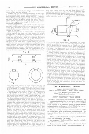
Feathers differ front keys, in that the boss is allowed to slide along the shaft, but at the same time revolves with it ; example, the change-speed gears in some types of steam wagons. Sometimes two feathers are fitted, and at other times four, and they are either sunk in the shaft in the ordinary way and held in place with countersunk screws (Fig.
4, A), or dovetailed as B. The continual wear these feathers are subjected to, in addition to the wear in the grooves, causes a slackness, or the feathers may become loose in the shaft. The latter trouble can sometimes he remedied by going round the edge of the seat with a caulkires tool, although this is only a temporary remedy, and the onl practical way to make a repair is to fit new feathers. New feathers must-be a driving fit in their seats, but not so tight that their edges will cut the sides of the seat, which would leave burrs underneath, thus preventing the feathers bed ding well down on the bottom—a very important !mint. Countersunk feathers ("Fig. 4, B) are fitted in the same as ordinary keys with the exception that their sides are at an angle. After the new feathers have been fitted, callip..sr care
fully right along over the tops of those diametrically opposite one another to make sure they are parallel, and calliper also along the keyways in the boss (C) to make sure. they are also parallel; this must be observed, otherwise the pinion may be a good fit in one place, and, where moved longitudinally, may become slack. The pinion can subsequently be tried in position, and if it will just pass over theends of the feathers, it can be driven on a little way with :t block of hard wood and a hammer ; hard places can be cased with a file. The pinion must be an easy tit on the feathers; if the work has been properly done, the feathers should bear all over their surfaces.
Cotters, in steam wagons, are principally used to connect the crossheads to the piston rods, the ends of the rods being tapered, and these ends fit into a taper socket, bored in the crosshead. A taper slot is cut through both for the receptiots of a cotter; this should be parallel on the flat sides, and tapered on the edges, which are left round to correspond with the round ends of the slots left by the drills. It will be noticed in Fig. 5 that the slots in the crosshead and rod do not regist:T, and it is very important that this clearance should exist, or the colter on being driven in may tighten itself up, at the same time allowing the rod to work loose in the crosshead. II the bore is not carried right through the crosshead, he careful to see that the end of the rod does. not bottom before it becomes tight on the taper. If the cotters are bent they must be made hot and straightened; the split pin hole should be close up under the crosshead, as this will check any tendency on the part of the cotter to work back. Sometimes the end of the rod is screwed with a fine thread and provided with a nut, which can be screwed up against the crosshead to start the rod out of the bore. Before driving the cotter home, be sure the nut is quite clear, or the cotter may tighten on the nut and leave the rod slack in the bore.