


Patents Completed.
Page 26
If you've noticed an error in this article please click here to report it so we can fix it.
METAL-TO-METAL CLUTCH.--j. D. Roots.—No. 6,835, dated March 21st, 1906.--A drum (At, A?-) is secured to the flanged end of a driving shaft (A). The driven shaft (B) carries a three-armed sleeve (C) fast upon it, and a second sleeve (I) slides upon the first sleeve when operated by a lever (J). The sleeve (1) engages levers (II), and one of these is pivoted to each of the arms (Cl). Mounted within the driving drum are two friction discs G), carrying pins (E, E) free to slide in sleeves (D) carried on each of the arms (Cl). The friction discs (F, G) are normally maintained in contact with the driven drum by springs (DI). When it is desired to disengage the clutch the levers
(II) are caused to withdraw the disc (F, 6) from the drum (Al, A2) by means of links connected to the discs by screweyes (1-12).
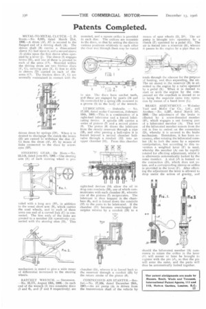
STEERING GEAR.—De Hora.—No. 13,119, dated June 6th, 1906.—The steering arm (E) of each steering wheel is pro sided with a long aim (BI), in addition to the usual short arm (B), which carries the road wheels, and to each of these arms one end of a curved link (C) is connected, The free ends of the links are pivoted to a member (D) operatively connected with the steering stem (II). This mechanism is stated to give a wide range of differential movement to the steering wheels.
RATCIIET WRENCH. — Stevenson. —No.-18,171, August 13th, 1906.—In each end of the wrench (1) two rotatable discs (5 and 6), and (7 and 8 respectively) are mounted, and a square orifice is provided in each disc. The orifices are eccentric to the discs, so that by setting the discs in various positions relatively to each other the clear way through them may be varied in sire. The discs have ratchet teeth, and these are engaged by pawls (14 and 15) controlled .by a spring (1() mounted in a groove (2)-in the body of the wrench.
-LUBRICATOR. Dubrulle, -No.
17,166, dated under Convention, February 10th, 1906.—This is a combination of a sight-feed lubricator and a forced lubricating device. A spindle (10) carries a series of pistons (7) and a second piston )8). The piston (8) draws the lubricant from the sunnly reservoir through a pipe {134 and after passing a ball-valve it is forced beyond a second chamber ballvalve through a conduit (12) into an upper chamber (11). From this chamber sight-feed devices (14) allow the oil to drop into conduits (16), one of which communicates with each chamber (6), wherein one of the pistons (7) reciprocates. The lubricant is thus trapped in the chambers (6), and is forced down the conduits (17) to the parts to be lubricated. If the chamber (11) becomes overcharged the surplus returns by a conduit (24) to a
chamber (15), when it is forced back to the reservoir through a conduit (25) by the return stroke of the piston (8).
COMPRESSED AIR STARTER.—Berliet.—No. 27,164, dated December 29th, 1905.—An air pump (A) is driven from the transmission shaft of the vehicle by
means of spur wheels (D, DI). The air pump is brought into operation by a Clutch (F) operated by a pedal (G). The air is forced into a reservoir (B), whence it passes to the, engine by a pipe that ex tends through the silencer for the purpose of heating, and thus expanding, the air. The air stored in the reservoir (B) is admitted to the engine by a valve operated by a pedal (K) When it is desired to start or work the engine by the compressed air the camshaft is moved so as to bring the requisite cams into operation by means of a hand lever (L).
BRAKE ADJUSTMENT. — Wolseley Tool and Motor Car Co., Ltd., and Another.—No. 5,297, dated March 5th, 1906.—The adjustment of the brake is. effected by a screw-threaded member 131), which engages a net forming part of a bifurcated member (A). That end of the bifurcated member remote from the nut is free to swivel on the connection (D), whereby it is secured to the brake mechanism. Heretofore, it has been necessary, after rotating the bifurcated member (A) to lock the same by a separate manipulation, but according to this invention a weighted lever (F) is used, whereby the member (Al can be rapidly rotated for effecting adjustment, whilst it is afterwards automatically locked by the same member. A stud WI is formed on the connection (D), which does not rotate, and a corresponding stirrup or orifice is provided in the lever (F). After effecting the adjustment the lever is allowed to drop under the action of gravity, and
should the bifurcated member (A) commence to rotate the orifice in the lever (E) will sooner or later be brought to register with the pin (el), so that the pin will enter the same, and the parts will thus be automatically locked together.