


Breaking Away from Cony on in Battery-electric Design
Page 26
Page 27
Page 28
If you've noticed an error in this article please click here to report it so we can fix it.
• By A. W. Haigh,
A.M.I.A.E.
DESIGNERS. of battery-electrics have not yet realized that their product is a special unit.iii the sphere of road transport and, as such, must receive the attention which its operating conditions demand.
Weight reduction has been emphasized before and, because of its paramount importance, will continue to be stressed as it affects the original purchase price, running costs, and speed and range of operation per battery charge.
The weight of the battery-eleCtric, when orthodox chassis layout is followed, has, possibly, been reduced to a minimum, but that which has been achieved is not sufficient. If the old ideas cannot bring about the desired result, then it is time that sound new ones—no matter how revolutionary—be given a trial.
It may be argued that now is not the time for experiments with unorthodox designs, but if, by the adoption of new ideas, costs can be cut and material saved, then they should he given serious attention.
Assuming that stressed body construction is out of the question--a reastmable assumption, as platform lorries must have a supporting frame, and a successful frameless commercial vehicle, of lower %eight than the normal, has yet to be produced in quantity—the essential units-of a batteryelectric are the body, frame, axles, brakes, motors, batteries and controller. It is to be noted that neither springs nor propeller shaft have been included. , The suggestion that two complete units can be dispensed with may appear to be sweeping, but the propeller shaft can be eliminated if the motor be made integral with the driving axle, Better still, however, would be the use of wheel motors when the mechanical differential, in addition to the propeller shaft, would. no longer be necessary. But wheel motors are not as yet widely used.
With the absence of a propeller shaft the cushioning effect on the drive is lost, but it trouble were to be experienced with axle shafts, crown wheel or pinion teeth, then a flexible coupling, such as the Layrub, Silentbloc or Metalastic, could be fitted between the output shaft of the motor and the driving-axle pinion.
Orthodox Suspension System , Can Be Dispensed With
Two outstanding features indicate that the springs can be dispensed with. In the first place,‘ the speed of the battery-electric vehicle is low and, secondly, road surfaces o-ver which most local-delivery vehicles operate are smooth. Hence the comparatively, high deflection of orthodox springs is unnecessary to acconfmodate the slight shocks induced by normal road surfaces.
Would it not be possible then, under these low-speed conditions, touse a vehicle without spring suspension, relying on the tyres to take up any road shocks? Considerable publicity has been given to all-rubber and rubberpnenneafie suspension systems, both of which have proved successful, and it should not he impossible to remove them Li-ow their orthodox positions, that is, from between the axles and frame, to a position between the road and wheels, or, in other words, let the tyres, which are a form of rubberpneumatic Suspension, take the place of springs.
The assessment of the springing value of tyres is a difficult problem. Its solution is possible only by experiment, but a brief examination of some of the properties of tyres should assist in a reasonable choice being made.
The qualities required are good cushioning capacity, lateral stability and low power absorption. The cushioning capacity ol a tyre is mainly dependent on the amatint of rubber in it, and the advantage taken of the high hysteresis value of this material. Then there is its internal pressure and the width of the wheel rim ; the latter governs wall height and, ignoring interna, pressure, the greater this height the snore resilient the tyre. .
Low-pressure covers contain more rubber than do the high-pressure types, and are, in general, more robust, so that with equal loads on the casings alone there would be less deflection of the low-pressure unit. Because of the additional rubber in the latter, however, cushioning should be about equal in both. Air pressure would reverse the action, so that the low-pressure tyre would deflect the •' greater amount. -Theory, then, suggests that low-pressure equipment holds a slight advantage in the matter of cushioning, but in practice the result might be entirely the opposite.
With regard to lateral stability, the governing factors are the same as.for cushioning. The high-pressure tyre is the more stable; hut high walls decrease stability. This decrease, however, is so little that itis -undetectable to -the occupants of a vehicle and can, therefore, be ignored.
As both high-pressure and low-pressure equipment give approximately the same cushioning and stability, the deciding factor, in the choice of tyres, is that of rolling resistance. Experiments carried out in this country, and DI America, show that this resistance is dependent on several factors. For instance, it increases in inverse ratio to the speed, that is, if the speed be doubled the rolling resistance is more than doubled. It has been recorded that high-pressure tyres offer less resistance to rolling than do the low-pressure type, to the extent of giving an increase in mileage of 15 per cent. and in speed of 7iper cent. These figures were obtained with a battery-electric vehicle.
The cord construction of a tyre controls rolling resistance, in that it increases with the number of plies. Rayon gives approximately 4 per cent. lower, resistance than does cotton, and a decrease in power absorption. up to 3i per cent., whilst worn tyres have only 84 per cent, of the resistance of new tyres.
Tyre Makers Can Help In Solving Important Problems It has been stated that the larger the rim the lower the resistance, an assertion which seenes to contradict expecta tions, because narrow rims, as already mentioned, mean increased wait height with decreased contact area between the tyre and road. This fact leads to the conclusion that narrow-base rims give the lower resistance. Finally, the composition of the rubber is a factor to be reckoned with ; an American manufacturer claims that the latest formula ensures a saving in current consumption of up to 30 per cent., an increased speed of up to 1i m.p.h.
From the, foregoing it Can be appreciated that tyre makers are by no means behind chassis manufacturers in their research to provide an ideal product, and that it should not be a difficult task for them to evolve a suitable high-pressure tyre to give both low rolling resistance and good springing.
Having eliminated orthodox springs, the next step is to provide a suitable frame. The normal "grid-iron " frame is well suited to the use of semi-elliptic springing, but it can be improved upon where suspension is left to the tyres. We have two axles which must be "tied " together to form a base upon which the body can rest.
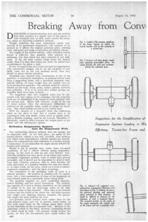
Why not, then, make use of the central, tubular backbone, as used on the " Q" battery-electric, to connect the axles, as shown in Fig. I? Here the entire frame, axles, and
suspension are contained in a simple 1-1 structure composed of three tubes. If wheel motors be adopted, the
frame would be at its simplest, the two cross members being plain tubes, with the ends of the front ones incorporating bushes to support the king-pins, whilst those of the rear tube might be swaged down and the ends turned to accommodate the wheel bearings. Further, they might be bored out to take separate stub axles.
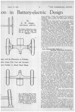
It has been mentioned before that wheel motors haye, as yet, to prove themselves, so that provision must be made to mount high-speed motors. Figs. 2, 3, 4 and 5 show layouts for both front and rear-wheel drives. Fig. 2 illustrates a front-axle drive, in which the cross tube forms the axle and reduction-gear casing, the drive being taken through constant-velocity universal joints. No mechanical differential would be necessary.
Fig. .3 is another front-wheel-drive arrangement, but, in this case, an orthodox motor is Shown bolted to the axle casing, which also forms the cros tube and incorporates
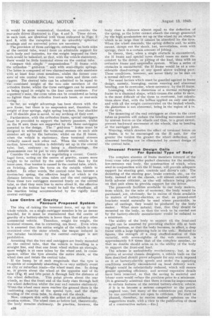
the usual mechanical differential. Whilst front-wheel drive is, a desirable feature fora battery-electric, •the use of constant-velocity joints is open to question, as they are by no means cheap and., further, are not in the Lest interests of weight reduction: Until the advent of wheel motors, it would be more economical, therefore, to consider the rear-axle drives illustrated in Figs 4 and 5. These drives, in each case, are identical with those indieated in .Figs, 2 and. 3, with the exception that no uriweildyspherical housings and no universal joints are necessary.
:The provision of three outriggers, extending on both sides of the central tube, woull form an admirable support for both body and batteries, for the weight imposed on their
'ends would be baladeed, so that, with the vehicle stationary, there' would be little torsional stress on the central tube. Compare this simple " suspensionless " H frame with the orthodox" grid-iron" unit with semi-elliptic springs. The latter is composed of two channel-section side members with at least four cross members,' whilst the former consists' of one central tube, two cross tubes and three outriggers. The central tube can be admitted to .be equal to the combined weight of the two .side members of the orthodox frame, whilst-the three outriggers can be assessed as being equal in weight -to the four cross members For argument's sake, the ,cross tubes can be considered as being no lighter than the orthodox front-axle beam, or rear-axle
. rasing.
• Soi far, no weight advantage has been shown with the new frame, but there is no suspension and, therefore, the weight of four springs, eight spring brackets, four shackles cod 12 shackle pins is saved, to say nothing of their cost.
Furthermore, with the orthodox frame, special outriggers 'must be .provided to support the battery panniers, whilst on the H unit these are supported by the three outriggers essential to the design. The " grid-iron" frame must be designed to withstand the torsional stresses in each side member set up by the batteries,' whilst on the H frame, when the vehicle is stationary, these torsional stresses virtually cancel each other out. When the vehicle is in motion, however, torsion is definitely set up in the central tube; but, contrary to being a disadvantage, the phenomenon can be put to very definite use..
Consider the vehicle to be negotiating a corner. Centrifugal force, acting on the centre of gravity, causes more weight to be carried by the outer wheels than by the inner ones, thus torsion is caused in the central tube, which, on tWisting, allows the tyres • on the outside wheels to
defleet. In other words, the central tube has become a torsion-bai spring, the effective length of which is the distance between the cross tubes and the end outriggers. Were these two outriggers mounted freely on the central tube, so that they were free to move about it, the effective length of the torsion bar would be half the wheelbase, all the reaction being accommodated by the rigidly fixed central outrigger.
Low Centre of Gravity Favours Proposed System The idea of :taking the torsional force, set up by the whole vehicle, on a single outrigger member is by no means fanciful, for it must be remembered that the centre of gravity of a battery-electric is lower than that of any other commercial vehicle. Therefore, weight for weight, the torsional stresses, due to cornering, are fewer.. Even when it is assumed that the entire weight of the vehicle is concentratedoVer the onter wheels, the torque induced in the tubular backbone by the central • outrigger Is not • prohibitive.
Assuming that the two end outriggers are freely mounted on the central tube, that the vehicle is travelling in a straight line, and that one front wheel strikes an obstacle, more we%ht is at once taken by the wheel and, in consequence, either the tyre absorbs the entire shock, or the wheel rises and twists the central tube.
If the bump be of such magnitude that the tyre is iecapable of completely absorbing it—a very unlikely event on city or suburban roads—the wheel must rise.' In doing so, it pivots about the wheel at the opposite end of its tube (Fig. 6) and lifts point A through half the distance of the wheel deflection. This point pivots about the rear wheels, so that the front end of the body rises through half .the wheel deflection whilst the rear end remains stationary. When,the wheel once more reaches the ground there is the cushioning capacity of the special.' tyre, and the slight bending of the cross tube, to damp out the shock.
Now compare this with the action.of An orthodox suspension system. The wheel rises as before but, theoretically, the body remains stationary. In practice, however, the A26 body rises a distance almost equal to the deflection of the spring, as the latter cannot absorb the energy generated . by the high, acceleration Set up in the wheel by an obstacle which is so large that it cannot be absorbed by the tyre. When the wheel descends, the spring deflects and, to some extent, damps out the shock, ,btit, nevertheless, even with springs, there is a-certain amount of jolting. In theory, then, when a single obstaele is encountered, the If frame and special' tyres should cause no more 'discomfort to the driver, or jolting of the load, than with an orthodox frame and suspension system. When a series of obstacles is encountered, the H frame would be at a considerable disadvantage at any speed above walking pace: These conditions, however, are never likely to be met on a normal delivery route.
The usual factors which must be guarded against in frame design, namely, lozenging, excess weaving and abnormal . bending, .can be overcome, where necessary, by the H frame.
Losenging, which is distortion of a normal rectangular frame to a diamond shape, which causes ,the axles to skew, is the Most difficult of the three to.overeome, but calculations show -that, with the billies applied on only one side, and with all the weight concentrated on the braked wheels, the elistortion is not abnormal, being in_the region of Iin. at the tyre.
The mounting of the end outriggers as close to the cross tubes as possible Will reduce the bending movement caused by uneven forces on the wheels and thus, to a great extent, prevent backward movement of the wheels, due to bending • at the outrigger joint.
Weaving, Which denotes, the effect of torsional forces on a frame, is to he encouraged on the H unit, for the greater the torsion the greater the wheel deflection., and abnormal bending can be eliminated by correct design of the central tube.
. Unusual Frame Design Calls
For Special Type of Body, The complete absence of frank members forward of the front cross tube provides perfect clearance for the modern, low-entrance van body, the construction of which, when ukd in conjunction with the H frame, will provide adequate support for steering gear, controls and driver's cab. The Mounting of the steering gear, brake controls, etc., on the body, instead of on the chassis,. will almost certainly call forth adverse criticism, as also will reliance being placed on that unit alone to provide support for the driver.
The .presswork facilities available to du.r body makers, from which, for the sake of economy, the body would be purchased, ,are, obviously, far in excess of those available ' to makers of battery-electrics, so that, as pressed-steel brackets: would naturally be used where practicable, in place of castings, they would be produced by the body maker. What more natural, then, that they should• be mounted on the body, so .that. the work .to be carried out by the battery-electric manufacturer would be reduced to
a minimum. .
The ability of the body to support all the front-end weight can be assumed by providing shallow sills at both top and bottom, so that the body becomes, in effect, a deep frame with a large lightening hole in the Web.. Reduced to . figures, the strength of a deep chatnel-seution of thin material, with seven-eighths of the web removed, is approximately 0.8 times that of the complete member, so that no doubts should arise, as to the ability .of the body to support the front-end load.
The scheme is undoubtedly revolutionary, • but, in the opinion of . several chassis designers, a vehicle built on the lines described should prove adequate for any work imposed . on it at battery-electric speeds and under the operating .conditions normally encountered on local delivery work: Weight would he substantially reduced, which will ensure greater operating efficiency, and several expensive details have been .removed, so that the saving in material and labour costs would reduce the purchase price to a' minimum. [It is generally admitted that there is room for improvement
in certain features of the .normal battery-electric vehicle. if it is to become a serioUs competitor to the petrolengined wan, but .many of the Contentions put. forivard by our contributors are open to criticism. We shall be pleased, therefore, to receive readers' opinions on the suggestions made, with a view to the publication of those of a constructive nature.—E.D1