


Power-assisted Steering
Page 56
If you've noticed an error in this article please click here to report it so we can fix it.
A Resume of Patent Specifications that Have Recently Been Published
A N interesting instance of American
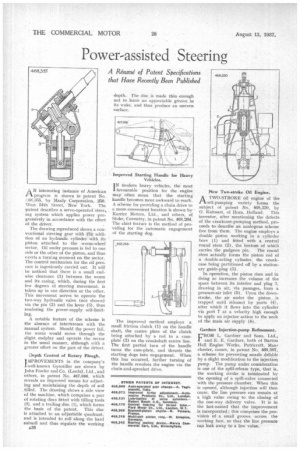
progress is shown in patent No. .'„68,355, by Manly Corporation. 2•10. \Veit 54th Street, New York. The patent describes a servo-operated steer,. mg system which applies power progressively in accordance with the effort of the driver.
The drawing reproduced shows a conventional steering gear with the addition of an hydraulic 'cylinder with, its piston attached to the worm-wheel sector. Oil under pressure is fed to one side or the other of the piston, and thus exerts a. turning moment on the sector. The control mechanism for the oil pressure is ingeniously carried out. It will be noticed that there is a small endwise clearance (1) between the worm and its casing, which, during the first few degrees of steering movement, is taken up in one direction or the other. This movement serves to operate the two-way hydraulic valve (not shown) via the pin (2) and the lever (3), thus rendering the power-supply self-limiting.
A notable feature of the scheme is the absence of interference with the manual system. Should the power fail, the worm would move through the slight endplay and operate the sector in the usual manner, although with a greater effort on the part of the driver.
Depth Control of Rotary Plough.
IMPROVEMENTS in the company's L well-known Gyrotiller are shown by John Fowler and Co. (Leeds), Ltd., and others, in patent No. 467,686, which reveals an improved means for adjusting and maintaining the depth of soil tilled. The drawing shows a side view of the machine, which comprises a pair of rotating discs fitted with tilling tools (2), and a trailing disc (1), which forms the basis of the patent. This disc is attached to an adjustable quadrant, and is intended to roll along the hard subsoil and thus regulate the working A38 depth_ The disc is made thin enough not to leave an appreciable groove in its wake, and thus produce an uneven surface.
Improved Starting Handle for Heavy Vehicles.
I N Modern heavy vehicles, the most favourable position for the engine may often mean that the starting handle becomes most awkward to reach. A scheme for providing a chain drive to a more convenient location is shown by Karrier Motors, Ltd., and others, of Stoke, Coventry, in patent No. 468,264. The chief feature is the method of providing for the automatic engagement of the starting dog.
The improved method employs a small friction clutch (1) on the handle shaft, the centre plate of the clutch being attached by a rod to a camplate (2) on the crankshaft centre line. The first partial turn of the handle turns the cam-plate, and thrusts the starting dogs into engagement. When this has occurred, further turning of the handle revolves the engine via the chain-and-sprocket drive. New Two-stroke Oil Engine.
ATWO-STROKE oil engine al the elf-pumping variety forms the subject of patent No.. 468,320, by 0. Kuhnast, of Horn, Holland. This inventor, after mentioning the defects of the crankcase-pumping method, proceeds to describe an analogous scheme free from them. The engine employs a double piston working in a cylinder bore (1) and fitted with a central round stem (2), the bottom of which carries the gudgeon pin. The round stern actually forms the piston rod of a double-acting cylinder, the crankcase being partitioned off by a stationary guide-plug (3).
In operation, the piston rises and in doing so increases the volume of the space between its interior and plug 3, drawing in air, .via passages, from a pressure-air inlet (5). I.Joon the downstroke, the air under the piston is trapped until released by ports (4), after which it flows into the cylinder via port 7 at a velocity high enough to apply an injector action to the neck of the main air supply (6).
Gardner Injection-pump Refinement.
FROM L. Gardner and Sons. Ltd., and E. E. Gardner, both of Barton Hall Engine Works, Patricroft, ManA chester, comes, in patent No. 468,307, a scheme for preventing nozzle dribble by a slight modification to the injection pump. The pump under consideration is one of the spill-release type, that is, the working stroke is terminated by the opening of a spill-valve connected with the pressure chamber. When this is opened, although injection will then cease, the line pressure can remain at a high value owing to the closing of the one-way delivery valve. It is in the last-named that the improvement is incorporated ; this comprises the provision of a small groove_ across the working face, so that the line pressure can leak away to a low value.