A Miscellany of NEW PATENTS
Page 76

If you've noticed an error in this article please click here to report it so we can fix it.
A Simple Hand-brake Lever. yurki have seen before hand-brake V V levers that have no trigger to actnate the pawl, but that described in
the specification No, 315,020, of P. E. Dadd, of 41a, Shakespeare Road, Bedford, appears to be one of extreme simplicity.
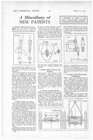
The lever is formed of two parts, the lower one actuating the shaft, or the extension to which the brake rod is attached, and terminating at the slotted portion ; also it carries a pawl which may be spring or weight-actuated. The second part is pivoted slightly below the slot. The pawl has' an upturned piece so arranged that it will engage with a projection below the upper lever.
On the lever being pulled to apply the brakes the pin comes to the end of the slot, so that the lever can act as if it were one ,piece, the pawl engaging in a notch where it will remain so long as the lever is not moved• forward ; when, however, it is moved in a forward direction it engages with the pawl and lifts it from the notches, so allowing the lever to return to the off position.
A Morse-chain Invention.
AN invention which is said to improve the silence and general running of the well-known Morse chain of the invertedtooth type is described in specification No. 302,910, by the Morse Chain Co., of New York State, U.S.A.
In the form of chain described, sliding as well as rocking movement takes place between the pintles which form the joints. As usual with chains 'of this class, of modern construction, the pintles extend the whole width of the chain, each being fixed to every alternate link, as, for instance, I is fixed to all links la, whilst 2 is fixed to all link.; 2a, in such a manner that no wearing movement takes place on the links themselves.
Besides the rocking movement which Las characterized this chain, there is a certain amount of sliding movement tak n50 jug place as each link bends to conform to the curve of the sprocket wheel.
In the left-hand view the chain will be seen as when it is in a straight line, the space at A indicating the slant on the flat surface, which holds towards the top, but when it bends, as in the right-hand view, 2 slidea downwards, entrapping a tapering film of oil as in
the well-known Michell bearing, thus ensuring more complete lubrication to the joint.
A Brake .Which Stores Up Energy.
AN inventor from Norway, Coom. Kittilsen, is responsible for the design of a brake described in specification No. 298,533, in which an arrangement is shown where a coil spring is wound up by the stopping of a vehicle, the stored-up power being released to assist in the restarting when required.
Having no experience of such devices, we would rather not commit ourselves by expressing any opinion on the invention.
A Brake-riveting Device.
THE device described in the Epecifica tion No. 315,159, of A. D. Powell and Joseph Bradbury and Sons Ltd., both of Braintree, Essex, is intended to make the operation of riveting the fibrous material to brake shoes an easier matter and to ensure the close adhesion of the fabric to the metal shoe.
The device takes the form of a machine which can be fixed to a bench or held in any other convenient way so that the plunger shown can be operated by means of a pedal lever, thin carrying a forked arm which presses on the material while the riveting operation is in progress.
The plunger which actually does the
riveting is described as being hit by a hammer for this purpose. It will be seen that the riveting plunger is cut away at one side so that it can clear the central rib usually found on brake shoes.
A Tractor with Three-point Suspension.
THE design of suspension shown in
the specification of Fiat Societa Anonima, of Turin, No. 310,794, is one that is intended to provide a better means whereby the wheels of a tractor can adapt themselves to uneven ground.
The arrangement is shown applied to a rear-driving axle which is provided with a differential casing to enable the worm, or other means for driving, to be situated to one side so as to provide for a central pivot.
Rubber buffers are provided to limit the movement when required. Two springs are employed, arranged as shown.


