


A MULTI-WHEELER ?OR ANY SURFACE
Page 58
Page 59
Page 60
Page 61
If you've noticed an error in this article please click here to report it so we can fix it.
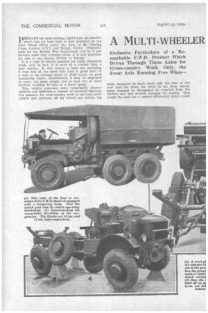
PERHAPS the most striking rigid-frame six-wheeler which has yet been built is that produced by the Four Wheel Drive Lorry Co., Ltd., of 46, Charing Cross, London, S.W.1, and Slough, Bucks. Originally built for the British War Department and by it put through some very arduous trials, it is now available for sale to any buyers, British or foreign.
It is a type of vehicle intended for really strenuous work, and, in fact, it is more of a tractor than a load carrier. It will convey a load not exceeding 3 tons and at the same time haul a gross load of fi tons at an average speed of 15-20 m.p.h. on good undulating roads; alternatively, it may be employed to carry the same weight and to haul two or more trailers, totalling 10 tons, at a lower speed.
This vehicle possesses some remarkable characteristics and embodies a number of patented features. For instance, for cross-country work or use over particularly soft surfaces, all six wheels are driven, but when employed on hard roads only the four at the rear take the drive, the drive to the front wheels being engaged or disengaged as required from the driver's seat and without stopping the vehicle. This avoids the need for a central differential which would nave increased the wheelbase by nearly 1 ft. The patented F.W.D. method of driving the rear axles which is utilized on the six-wheelers previously built has been modified on this particular model with the object of reducing the wheelbase and the length of the chassis to the smallest practicable dimensions; this has resulted in obtaining a chassis in which the wheelbase from the front axle to the centre of the bogie is 10 ft., whilst the distance between the rear axles is only 4 ft.
The propeller shaft is mounted well above the axles and the drive to the bevel pinion is behind the axle in each case, so that the universal joint of the leading axle is kept well back, thus enabling a comparatively long shaft to be employed.
Another very important feature which has enabled the transmission to be kept comparatively light and compact is the epicyclic final-reduction gear carried within each wheel and giving a reduction ratio at this point of 3 to 7.
Low-pressure pneumatic tyres are fitted all round, those at the front being pumped to 45 lb. per sq. in., whilst at the rear the pressure of each is 35 lb.; they are of Dunlop make. It will be seen that two spare wheels are carried across the chassis behind the petrol tank, and a neat Tasker patent hoist winch gear enables them to be raised or lowered with ease.
Accessibility to the engine is permitted by swinging outwards the near-side front wing; only two nuts require to be unscrewed for this purpose.
Still tubes are employed for the radiator, which has a neat shutter control mounted on the dash. The appearance is improved by curving the top of the dash in the same, manner as the radiator top tank.
• Power is provided by a Dorman six-cylindered engine of the &LILL. Mark 2 pattern,,developing 78 b.h.p. at 2,000 r.p.m., and 57.5 b.h.p. at the normal speed of 1,300 r.p.m.
The main gearbox is assisted by a secondary reduction box of the sliding-gear type which is spigoted into its rear; this secondary box gives a reduction of 2.78 to 1. In the high ratio, the reductions and the road speeds at 1,300 r.p.m. are as follow :—Top, 10 to 1 (15.6 m.p.h.) ; third, 17.5 to 1 (8.9 m.P.11.) ; second, 29.8 to 1 (5.3 m.p.h.) ; first, 44.6 to 1 (3.5 m.p.h.); reverse, 44.6 to 1 (3.5 m.p.h.). With the low ratio the corresponding figures are':—Top, 27.8 to 1 (5.6 m.p.h.) ; third, 48.6 to 1 (3.2 m.p.h.) ; second, 82.7 to 1 (1.9 m.p.h.) ; first, 123.7 to 1 (1.3 m.p.h.) ; reverse, 123.7 to 1 (1.3 m.p.h.). Owing to the particularly low ratio which can be obtained, it is essential to watch the engine speed very carefully, and this is permitted by a revolution counter mounted on the instrument board. The highest tractive effort is 5.27 tons. The drive to the front axle is taken from the rear of the mainshaft by a sliding gear on a layshaft, and thence by skew gears to the front axle; this gives a straight line for the shaft from gearbox to axle and it is this drive which is disconnected as required.
An extra countershaft is provided for driving a powerful winch, although, of course,
such a device might not be required on any but vehicles designed for all-round use. The•
winch drive is engaged by a sliding gear. It is equipped with 350 ft. of 1-in.-diameter steel rope and the pull varies from 7.32 tons for the top layer to 9.5 tons for that at the bottom; the rope speed at maximum torque is 51 ft.-mins. The rope is carried underneath the floor of the body to the rear end of the chassis and is paid on to the drum by a particularly neat automatic gear. This consists of a chain carried horizontally over two sprockets, one of the pins being elongated and connected to a sliding carriage which is mounted on two guide tubes. At one end of the chain is a tensioning device, and the chain-driving sprocket is rotated by a worm. The elongated pin carries the sliding carriage backwards and forwards in front of the drum and proves an effective laying-on device.
Suitable twin pulleys and rollers are mounted at the rear of the machine as well as at the front and rear corners of the frame on the right-hand side, so that the rope may be paid out forward to pull the machine through soft ground if this be necessary. At the near side of the winchdriving gear is a handwheel, this being utilized for freeing or engaging a dog clutch in tne drive to the drum; thus the rope can be paid out without any gear being in mesh. A brake is, of course, provided for the drum.
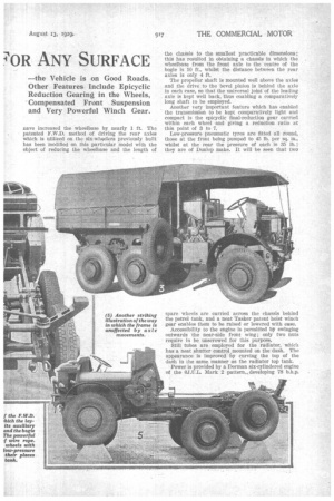
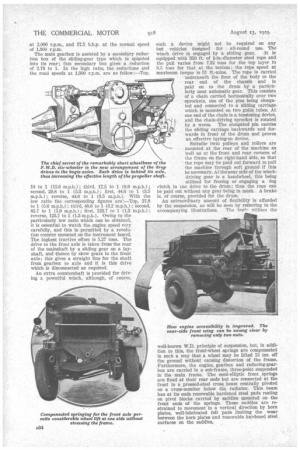
An extraordinary amount of flexibility is afforded by the suspension, as will be seen by referring to the accompanying illustrations. The borie utilizes the well-known W.D. principle of suspension, but, in addition to this, the front-wheel springs are compensated in such a way that a wheel may be lifted 12 ins, off the ground without causing distortion of the frame. Furthermore, the engine, gearbox and reducing-gearbox are carried in a sub-frame, three-point suspended in the main frame. The semi-elliptic front springs are fixed at their rear ends but are connected at the front to a pressed-steel cross beam centrally pivoted on a cross-member below the radiator. This beam has at its ends renewable hardened steel pads resting on pivot blocks carried by saddles mounted on the front ends of the springs. These saddles are restrained to movement in a vertical direction by horn plates, well-lubricated felt pads limiting the wear between the horn plates and renewable hardened steel surfaces on the saddles, To afford the maximum possible body space in such a machine forward control is provided, and the connection from the change-speed lever to the gearbox is particularly neat and effective. The lever is fulcrumed in a fork which is free to turn. The end of the lever is extended rearward into a cup formed at the end of the short lever mounted on the selector shaft; by this means the shaft can be moved in and out or rotated.
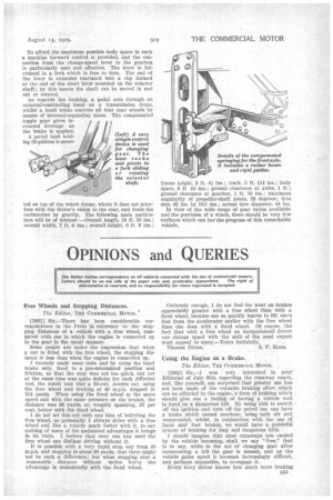
As regards the braking, a pedal acts through an external-contracting band on a transmission drum, whilst a hand brake controls all four rear wheels by means of internal-expanding shoes. The compensated toggle gear gives increased leverage as the bra.ke is applied.
A petrol tank holding 50 gallons is moun
ted on top of the winch frame, where it does not interfere with the driver's vision to the rear, and feeds the cartruretter by gravity. The following main particulars will be of interest :—Overall length, 18 ft. 10 ins.; overall width, 7 ft. 6 ins.; overall height, 6 ft. 9 ins.;
frame height, 3 ft. 44 ins.; track, 5 ft. 11iins.; body space, 8 ft 10 ins.; ground clearance at axles, 1 ft.; ground clearance at gearbox, 1 ft. 10 ins.; maximum angularity of propeller-shaft joints, 23 degrees; tyre size, 42 ins. by 10.5 ins.; actual tyre diameter, 44 ins.
In view of the wide range of gear ratios available and the provision of a winch, there should be very few surfaces which can bar the progress of this remarkable vehicle.