


New Valve Gear for Two-strokes
Page 36
If you've noticed an error in this article please click here to report it so we can fix it.
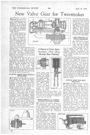
ALTHOUGH intended mainly for use in aircraft, an engine shown in patent No. 567,463 will doubtless be of general interest on account of its low weight. The patentee is J. Jameson, Chessington Lodge, Spring Street, Ewell, Surrey.
The engine operates on the two-stroke cycle, and the chief novelty lies in the valve arrangements. The engine is built up from horizontally opposed pairs of cylinders, and the drawing shows one of such pair. The valve is a piston-like structure (1), which works in a small extension of the
cylinder bore. The valve is reciprocated by a rocker (2), which is attached to a shaft carrying a second similar rocker (8). The latter is driven by a push rod (4) actuated by an eccentric (5) on the crankshaft.
The main piston and the valve work in opposition, so .that , much of the inertia force is cancelled out. The short connecting rod between the push-rod and its eccentric amplifies the " obliquity " effect, so that a very sharp
action is given to the valve. The engine operates on conventional prin..ciples, the exhaust leaving via a ported belt (6) in the cylinder wall, whilst the new charge enters via ports (7).
STARTER PINION WITH HOLD-IN MECHANISM
AN improved starter pinion is shown in patent No. 567,440, by Bendix Aviation Corporation, South Bend, Indiana, U,S.A. The design is intended especially for heavy duty engines 'and embodies a means for holding -the pinion in mesh. until the engine has reliably settled down to running.
The drawing shows the pinion in the in-mesh position with the flywheel ring (I). The pinion itself is freely mounted on a nut-collar (2), a driving connection being 'established during end-piessure by a series of fine clutch teeth (3). A spring-returned sliding pin (4) is thrown by centrifugal force into the position shown, and prevents the retraction of the pinion, leaving, however, enough end play for the disengagement of the clutch teeth.
In the event of a false start, the nut sleeve backs away up to the catch-pin, leaving the pinion tree to overrun while the engine makes a
sporadic fire. The engine then slowing, the starter again applies •a drive so soon as its speed exceeds that of the. pinion, at which moment the clutch parts are again screwed together. No permanent disconnection can occur until the starter speed falls sufficiently to allow the centrifugal catch-pin to retreat into the spindle.
IMPROVEMENTS IN RUBBERBUSHED' UNIVERSAL JOINTS TO prevent the resilient bushes of a transmission joint from forming creases which might develop into cracks is the object of a modified shape of bush shown in patent No. 567,477, by Thompson Products Inc., Cleveland, Ohio, U.S.A.
The drawing shows sufficient of a transmission joint to illustrate the scheme. The rubber bush is provided with bondedon inner and outer sleeves, which are gripped by the metal parts of the joint. Each bush is made with deep annular grooves or cuts (1), which form rolling faces when the joint is subjected to angular deflection. The proportions of the grooves are such that their innermost ends never become opened, so that there is no possibility of cracks forming at these points. The design is claimed to permit a much greater deflection than existing types will give, and to possess a longer working life, without, of course, the need for lubrication.
NEW PRINCIPLE IN SHOCK-ABSORBERS
A REBOUND damper rI of the hydraulic type, employing a rubber vessel for the resilient member, forms the subject of patent No. 567,396, from C. Vickers, Buffalo, New York, U.S.A. Although intended immediately for military purposes, the device is stated to be equally suitable for other and lighter duties.
The drawing shows the arrangement as applied to the ,landing wheels of an aircraft. The piston (1) receives the shock and transmits it to the fluid, via the usual cup-washer. The, up-stroke forces fluid past a one-way valve (2) and into a multi-ply rubber bag (3), which acts as the opposing. spring. The bag is trapped in a lengthwise direction, but is free to expand diametrically up to the limit of its confinement. The speed of the return stroke is governed by the setting Of an adjastable backleak (4), through which the fluid must, perforce, return.
SPECIAL BODY FOR MILK DELIVERY
PATENT No. 567,449 refers to pedestrian-controlled electric milk vehicles, and describes modifications to the bodywork which are intended to facilitate the handling of the crates. The patentee is S. Hole, Yew Tree House, Albourne, Hassocks, Sussex. The chief feature is that an iron framework is provided to form runners for the crates, so that the lower ones can be pulled out like a drawer without „disturbing the others. The crates themselves are of the standard type, and advantage is taken of their small projections (provided for easy stacking) to form a stop to limit the outward movement. The arrangement is not, of course, confined to any particular type of vehicle.