


T HE new L.B.-type Thornycroft chassis, intended expressly for the accommodation
Page 16
Page 17
Page 18
Page 19
If you've noticed an error in this article please click here to report it so we can fix it.
of 0030-seater bus body, was in an advanced stage of design in the autumn, but, with deliberate intent, a few extra months have been devoted by Mr. Tom Thornycroft and his designing staff to the consideration of the special features, in each of which, in view of modern trend, there was a moot point. The predilections of the user do. not always agree with those of the designer, but heed must be paid to them because advance often lies that way, bides which it is the user who best knows the public for whom he is catering.
At the same time, the Manufacturer, for his own ultimate good and for the benefit of 'the user, desires that the chassis which he offers shall be practical in every sense, moderate infirst cost, economical to run, and, more important still, easy to maintain and essentially reasonable in cost of such maintenance.
The manufacturer also has to remember that, having sold a chassis, he is no longer master of its destiny or controller of its career. Equipped as a bus, it may be put to easy work in a district that has no serious hills and where overloading is a crime unknown. It may have a paragon of a driver and come under the control of a model fleet engineer. On the other hand, it may go into an area where brakes and gears have to be in constant use, where overloading is a common incident of operation, where the driver is rough, and attention to the claims of the chassis is as sparse as turf in an arid region.
It is because employment for the new L.B. chassis will be found in all parts of the country .and in various places overseas that it baS been built with an ample factor of safety in every one of its details, and, whilst • proved lightweight materials have been used wherever suitable and every ounce of dispensable weight has been cut out, the maintenance of the desired margin of safety has brought the bare* chassis to 56 cwt., assuming that a body of reasonable weight, say 25 cwt., is mounted on the chassis, a vehicle weight of 4 tons 1 cwt. is arrived at, which is, therefore, 6 cwt. outside of the 3 tons 15 cwt. recommended by the Departmental Committee on the Taxation and Regulation of Road Vehicles (second interim report, April 12th, 1922) for vehicles on pneumatic tyres to be allowed to run at 20 miles per hour. If the committee's recommendations are adopted without modification (our own tpinion is that the weight limit should be increased to 41 tons), the permitted speed of a vehicle of the weight outlined for ' the Thornycroft would be 16 miles per hour.
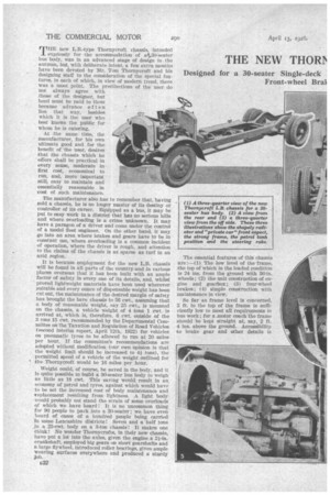
Weight could, of course, he saved in the body, and it is quite possible to build a 30-seater bus body to weigh as little as 18 cwt. This saving would result in an, economy of petrol and tyres, against which would have to be set the increased cost of body maintenance and ceplacement resulting from lightness. A light body would probably not stand the strain of some overloads of which we have heard! It is no uncommon thing for 90 people to pack into a 30-seater ; we have even heard of cases of a hundred people being carried hi some Lancashire districts! Seven and a half tons jn a 25-cwt. body on a 3-ton chassis! It makes one think! No wonder Thornycrofts, in their new chas.sis, have put a lot into the axles, given the engine. a 21-in. crankshaft, employed big gears on short gearshafts and a large flywheel, introduced roller bearings, given ample wearing surfaces everywhere and produced a sturdy job. The essential features of this chassis are :—(1) The low level of the 'frame, the top of which in the loaded condition is 24 ins, from the ground with 36-in. wheels; (2) the unit construction of engine and gearbox; (3) four-wheel brakes; (4) simple construction with maintenance in view.
So far as frame level is concerned, 2 ft. to the top of the frame is sufficiently low to meet all requirements in bus work ; for a .motor coach the frame should be kept straight at, say, 2 ft. 4 ins, above the ground. Accessibility to brake gear and other details is
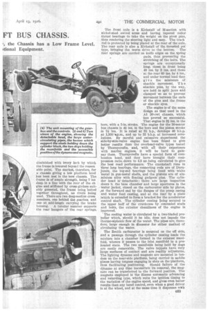
diminished with every inch by which the frame is lowered beyond the reason able point. The market, therefore, for a chassis giving a low platform level has been met in the new chassis. The frame is of ample strength, being 7 ins deep in a line with the rear of the en gine and stiffened by cross-girders suitably gusseted, the frame being 'bolted together throughout, no rivets being used. There are two deep-section cross members, one behind the gearbox and one at mid-length carrying the brake housing. A tubular member supports the rear hangers of the rear springs. The front axle is a Kirkstall of H-section with nickel-steel swivel arms and having tapered roller thrust bearings to take the weight on the pivot pins, thus rendering the steering light and easy. The track rod is protected by being placed at the rear of the axle. The rear axle is also a Kirkstall of the invented pot type, bringing the worm drive to the bottom. ' The rear springs are carried on knife edges on the spring pads, thus preventing the stretching of the bolts. The Springs are exceptionally long, those in front being 48 ins. by 3 ins, and those at the rear 60 ins. by 4 ins., and under normal load they give the minimum of shackle movement T he shackle pins, by the way, are held in split jaws and clamped so as to prevent movement between the ends of the pins and the frame or shackle eyes.
The engine is of the same design as that used in the Al 30-cwt chassis, which has proved so successful. That engine is 31 ins. in the bore, with a 5-in. stroke. The engine for the 30-seater bus chassis is 41 ins, in the bore and the piston stroke is 5i ins. It is rated at 35 h.p., develops 46 b:h.p. at 1,500 ',p.m., and up to 55 b.h.p. at increased revolutions. By careful and extensive experiment the side-by-side-valve engine has been found to give better results than the overhead-valve types tested by Thornycrofts, and, with. all their experience with marine engines, it will be bard to gainsay them. Thornyerofts have a special form of combustion head, and they have brought their compression ratio.down to 4.3 as ,being calculated to give the best road performance. The crankshaft runs in three long bearings, the connecting rods are of Duraiumin, the big-end bearings being lined with white metal in gun-metal shells, and the pistons are of aluminium alloy with floating gudgeon pins. The cylinder head is' detachable ; there are large inspection doors h. the base chamber and large apertures in the water jacket, closed on the carburetter side by plates, aI the forward end by the flanges of the pump casing and water feed casting, and at the rear by a plate ;which is extended to form a bracket for the accelerator control shaft. The cylinder casting being secured to the upper half of the crankcase by concealed studs and bolts, the exterior cleanliness of the engine is improved.
The cooling water is circulated by a two-bladed propeller which, should it be idle, does not impede the thermo-siphonic flow of the water. The pipes are, therefore, large enough in diameter for either method of circulating the water.
The Zenith carburetter is mounted on the off side, and a passage through the cylinder casting leads the mixture into a chamber formed in the exhaust manifold, whence it passes to the inlet manifold in a preheated state. The two manifolds being held by dogs ,are easily removable. The valve tappets have very large surfaces of contact and are readily adjustable. The lighting dynamo and magneto are mounted in tandem on the near-side platform, being carried in saddle pieces having tongues engaging in slots on the platform, thus facilitating positioning. Should failure of the dYnamo at any time necessitate its removal, the magneto can be transferred to the forward position. The magneto employed is the Simms automatic advancing and retarding type, which suits the ignition timing to the variation of the engine speed, and gives even better results than any hand control, even when a good driver is at the wheel, and at the same time it dispenses with the need for connecting rods and levers and it eliminates the need for attention to timing. The. dynamo and magneto shaft is driven through gearing from the crankshaft, and the cooling fan by belt. The exhaust valves are of stainless steel.
Lubricating oil is forced by a pump located in the sump and driven from the camshaft, the pump and drive being removable as a unit. All the oilways are cast in the casing, the only external pipe being the one taken to the gauge on the dash. The oil is fed to the main journals and through oilways drilled in the crankshaft to the big-ends. There is a large and convenient oil-filling orifice, and the level is indicated by a dip rod.
Cleverness in design is shown in"the way in which the accelerator pedal has been coupled to the throttle with a small number of parts and with a simple means for holding the throttle open at the minimum point.
The engine and gearbox form a unit, and it may be said that Thornycrofts are convinced that this system is sound. Perfect alignment is ensured from the start, the ingress of dust and dirt to clutch and joints between en4I4 ne and gearbox is prevented and, if attention be called for, it is an advantage to have the unit out, so as to be able to deal with it on the bench, although, as a matter of fact, much can be done n situ. It is claimed that, in from 1 to 2 hours, the unit can be removed from the chassis, the clutch examined and the clutch plate replaced if necessary and the unit again put in Position and Coupled up. The gearbox and clutch shrouding can be removed without affecting the engine, if desired. The unit system has proved so successful and popular on the 30-cwt. chassis that its employment is being extended on Thornycroft chassis. The unit, by the way, is carried at three points—at the front in a trunnion, supported on a rubber block held by an inverted 1j-shape stirrup, and bolted rigidly to two brackets at the rear. The gearbox gives four forward speeds, the control lever being disposed centrally.
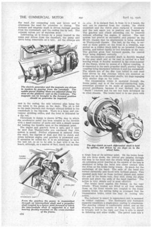
The intermediate propeller shaft is flexibly coupled to the gear shaft and at its rear is carried in a ball bearing whioh is flexibly mounted in the cross-member of the frame, whilst by means of a Spicer coupling, it is connected to the main propeller shaft, another Spicer coupling being interposed between it and the wornashaft. The wheels are of the disc type bolted to cast steel hubs driven by dog clutches which are mounted on splines Cut on the differential shafts, six dogs engaging with similar dogs on the hubs.
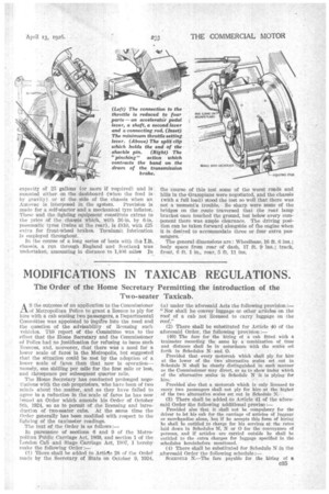
The transmission brake is operated through the brake pedal, and is of the 'external-contracting type, somewhat peculiar in its mode of operation, but of proved excellence, because it was devised for the " " tractors and its use has been developed on to other chassis. The brake band is in one piece with a hinge loop at its midway point. On the brake housing are three studs, the central foie passing through the loop in the band and the others being just outside. An adjusting screw bearing on the outside of the loop is employed to bring the band into closer contact with the drum as the brake lining wears. So much for the anchorage of -the band. The ends of the band are turned outwardly and faced with inclined planes. Two opposed pads bear on these inclined planes and, under the pull of the brake rods, they slide along the plane pieces and pinch the ends of the band together. The action is very simple and is most effective.
The brake lever applies the brakes on the rear wheels. When brakes are fitted to all four wheels, those on the front wheels are coupled to the transmission brake, the setting being so arranged that the transmission brake takes the lead in coming into action.
The radiator is smart in appearance and is mounted on rubber cushions. The dashboard and footboard supports constitute a single-piece casting in aluminium. The steering column is comfortably raked, and as the steering is mounted outside of the frame, the driver is brought 'well to the right and thus is able to signal to following and other traffic. The petrol tank has a
capacity of 25 gallons (or more if required) and is mounted either on the dashboard (when the feed is by gravity) or at the side of the chassis when an
Autovac is interposed in the system. Provision is made for a self-starter and a mechanical tyre inflator. These and the lighting equipment constitute extras to the price of the chassis whieh, with 36-in. by 6-in. pnemnatic tyres. (twins at the rear), is £810, with £25 extra for front-wheel brakes. Tecalamit lubrication is employed throughout..
In the course of a long series of "tests with the t.E. chassis,. a run through England and Scotland was undertaken, amounting in distance to 1,406 miles In
the course of this test some of the worst roads and hills in the Grampians were negotiated; and the chassis (with a full load) stood the test so well that there was not a -moment's trouble. So sharp were some of the bridges on the route traversed that the rear. lamp bracket once touched the ground, but below every component there was ample clearance. The driving position can be taken forward alongside of the engine when it is desired to accommodate three or four extra passengers. "
The general dimensions are: Wheelbase, 16 ft. 6 ins.; body space from rear of dash, 17 ft. 9 ins.; track, front, 6 ft. 1 in., rear, 5 ft.. 11 ins.