


A Tractor Variable
Page 56
If you've noticed an error in this article please click here to report it so we can fix it.
Steering Gear
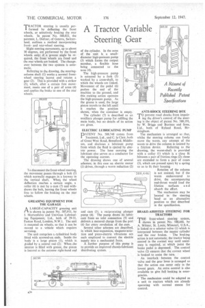
'TRACTOR steering is usually perI formed by deflecting the front wheels, or selectively braking the rear wheels. In patent No, 588,022, the patentee, L. Dufour, of Geneva, Switzerland, outlines a method incorporating frontand rear-wheel steering.
Slight steering movements, up to about 30 degrees, are performed by the front wheels only if a greater angle be required, the front wheels are freed and the rear wheels are braked. The changeover between the two systems is automatic.
Referring to the drawing, the steering column shaft (1) works a normal frontwheel steering layout and 'rotates a gear (2). This is ptovided with a striker (3), which, after a certain free movement, meets one of a pair of arms (4) and applies the brake to one of the rear wheels.
To disconnect the front-wheel steering, the movement passes through a bolt (5) which normally engages in ,a keyway in the vertical shaft. When the wheel deflection reaches a certain angle, a roller (6) is met by a cam (7) and withdraws the bolt, leaving the front wheels free to follow, the braking on the rear wheels.
GREASING EQUIPMENT FOR THE GARAGE
A LARGE-CAPACITY greasing unit
is shown in patent No. 587,911, by I. Martonfalvy and Uni-Gun Lubricating Equipment; Ltd, both of 29-31, Euston Road, London, N.W.1. The unit is mounted on wheels; so that it can be moved to a vehicle which requires servicing.
The unit comprises a cylindrical body fitted with screwed-on ends. Inside the body is a large •piston (1), which is. guided by a central rod .(2): When ,the interior is filled with grease, the piston is located at the extreme right-hand end of the cylinder. in the nose of the unit is a smalldiameter high-pressure pump (3) which forms the output member, a flexible hose being connected to the nose (4).
The high-pressure pump is actuated by a fork (5) worked by a cross-shaft, to which the wheels are linked. Movement of the pedal (6) pushes the end of the machine to the ground, and this rocking action operates the high-pressure pump. As the grease is used, the large piston travels to the left until it reaches the position shown, when the container is empty.
The cylinder (7) is described as an auxiliary plunger pump for refilling the main body, but no details of its action are given.
ELECTRIC LUBRICATING PUMP DATENT No. 588,748 comes from Tecalemit, Ltd,, and C. le Clair, both of Great West Road, Brentford, Middlesex, and discloses a lubricant pump from which the fluid is ejected by electric power. The hose carrying the lubricant also serves as a conductor for the operating current.
The drawing shows one of several schemes; in this case an electric motor (1) drives, through a worm reduction (2) and cam (3), a reciprocating plunger pump (4). The pump draws its lubricant from an inlet connection (5) and delivers a metered charge from the port (6) for every revolution of the cam.
Several .other schemes are described, in which heat-expansion, magneto-striction and piezo-electric vibrations are each employed to convert the electric supply into a mechanical force.
A .further purpose of this pump is to provide an improved chassis-lubricant distributing system. ANTI-SHOCK STEERING BOX
T.° prevent road shocks from impairing the driver's control of the steering is the object of patent No. 588,191, by W. Briggs and Burman and Sons, Ltd., both of Ryland Road, Birmingham.
The mechanism is arranged so that, whilst the steering column can freely move the worm, any attempt of the worm to drive the column is resisted by
a friction device. Referring to the drawing, the worm-shaft is provided with a collar (1) which is a close fit between a pair of friction rings (2); these are extended to form a pair of cones (3), which are pressed apart by a spring so as to fit their housing Rotation of the column is not resisted, but if the worm endeavoured to drive, the accompanying end-thrust would load the friction surfaces an d absorb the effort.
The mechanism may be located in the steering head as an alternative position to that ddscribed in the specification.
BRAKE-ASSISTED SILERING FOR TRACTORS front-wheel steering system, shown in patent No. 588,446. by A. Milster, St. Louis, Missouri, U.S.A., is linked to a selector valve (1) which is interposed between the master cylinder and the rear brakes. The braking action is not automatic, the tractor being steered in the normal way until assistance is required, at which point the brake pedal is depressed. The control valve (2) ensures that the correct wheel is braked to assist the turn.
An interlock between the control valve and the gear lever is arranged so that the action can occur only in the lowest gears. An extra control is also available to give full braking in emergencies.
The mechanism could be adapted as a unit to tractors which. are already operating with normal means for control.