


Factors Affecting ACCURATE CONTROL
Page 39
Page 40
Page 41
If you've noticed an error in this article please click here to report it so we can fix it.
By J. PICKLES, A.M.I.Mech.E.
IN the two preceding articles, the importance of tyre characteristics and axle alignment and mounting was discussed. Body roll and its effect must now be considered, and the inter-relationship between roll slip angles. Although not dangerous in itself, roll is usually held to be undesirable because of its bad effect on an ill-designed chassis.
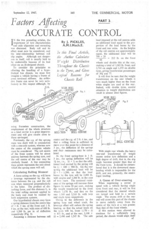
To consider the principles as affecting the handling of a hypothetical bus chassis, we must first imagine a vehicle having a frame of great torsional stiffness. An orthodox frame can never be very satisfactory in this respect although, by using frameless construction, the employment of the whole structure as a load carrier is a great improvement and will give results close to those envisaged.
Previously, the c.g. of the sprung mass was dealt with in conjunction with a one-axle system, whereas now the centre of the complete vehicle must be considered. The roll centre of the front system will be about midway between the spring eyes, and the roll centre of the rear may be similarly found. A line connecting these points represents the axis about which the sprung mass will roll.
Calculating Rolling Moment A force acting on the e.g. will have a leverage represented by the distance between the c.g. And the roll axis when measured perpendicularly to the latter. The product of disturbing force, and this distance L, is the total rolling moment applied to the body and must be resisted by both suspension systems.
Our hypothetical chassis may have a spring distance from the centre line of 1 ft. 3 ins. at the front and 1 ft. 8 ins, at the rear, with rates of 600 lb. and 1,200 lb. per in. of deflection respectively (Fig. 1).
Assuming a distance between roll centre and the e.g. of 2 ft. 6 ins., and that a rolling force is sufficient to move over this point by a distance of 3 ins., the deflection of the springs and their resistances may be calculated.
As the front spring-base is 1 ft. 3 ins., the spring deflection will be ins., i.e., ill x 3, so that the additional load carried by the spring will be LI x 600 = 900 lb. On the rear siring the additional load will be x 3 x 1,200, so that the load borne by the tyre will be 2,400 lb. with singles and 1,200 lb. in the case of twin. rears. The torsional resistance of the springs will increase these figures by some 30 per cent., making the weight transferred to the front wheels 1,170 lb., and that on the rear 1,560 and 3,310 lb with twin and single tyres respectively.
Owing to the difference in the spring base and wheel track, the leverage effect will reduce the spring loading, so that the actual loads on the tyres will be, front 1,170 x itt --851 lb., and at the rear, 3,100 x
= 2,490 and •1,245 lb. The side load imposed at the roll centres adds an additional load equal to the proportion of the load borne by the front and rear axles. As the heights of the roll centres are approximately equal, the additional load will be wheels and double this at the rear, making a total of 1,063 lb. front, and 2,710 on single and 1,355 on double tyres, giving transference percentages of 38i and 77.
It will thus be seen that the weight transference on the rear wheels is very much higher than on the front when singles are used at the rear. Indeed, with double tyres, careful attention to weight* distribution can result in almost ideal figures.
With single rear wheels, the heavy rear-end transference of weight causes undue tyre deflection and a high degree of drift, that is, the slip angle becomes greater than that of the front tyres. It should be remembered that it is the downward massloading which is responsible for the drift, and not, primarily, the centrifugal loading.
A Cause of Over-steering
When negotiating a corner at speed with a vehicle having single tyres front and rear, it will he first considered that the steered wheels are turned and held to a certain angle. The excess drift at the rear end will cause this part of the chassis to move radially away from the centre of the turn at a rate greater than that of the front wheels.
if this motion were allowed to continue for a sufficiently long period, the chassis would align .itself B5
radially towards the turn centre. In practice, this motion is checked by gradually turning the wheel towards the straight-ahead position. Oversteer is thus a feature of normally sprung vehicles, although twin rear tyres can cancel out such troubles.
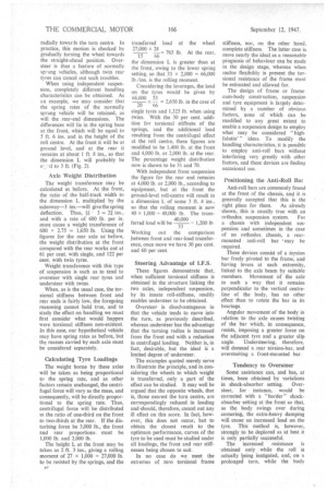
When using independent suspension, completely different handling characteristics can be obtained. As an example, we may consider that the spring rates of the normally sprung vehicle will be retained, as will the rear-end dimensions. The differences will lie in the spring base at the front, which will be equal to 5 ft. 6 ins, and in the height of the roll centre. At the front it will be at ground level, and at the rear it remains at about 1 ft. 8 ins., so that the dimension L will probably be
.al to 3 ft. (Fig. 2).
Axle Weight Distribution
The weight transference may be calculated as before. At the front, the ratio of the half-track width to the dimension L multiplied by the sidesway-3 ins.—will give the spring
deflection. Thus, • 3 = 21 ins., and with a rate of 600 lb. per in. must cause a weight transference of 600 x 235 = 1,650 lb. Using the figures for the rear axle as before, the weight distribution at the front compared with the rear works out at 61 per cent. with single, and 122 per cent. with twin tyres.
Weight transference with this type of suspension is such as to tend to oversteer with single rear tyres and understeer with twins.
When, as is the usual case, the torsional stiffness between front and rear ends is fairly low, the foregoing reasoning cannot hold true, and to study the effect on handling we must first consider what would happen were torsional stiffness non-existent. In this case, our hypothetical vehicle. may have spring rates as before, but the masses carried by each axle must be considered separately.
Calculating Tyre Loadings
The weight borne by these axles will be taken as being proportional to the spring rate, and as other factors remain unchanged, the centrifugal force will vary as the mass, and consequently, will be directly proportional to the spring rate. Thus, centrifugal force will be distributed in the ratio of one-third on the front to two-thirds at the rear. If the disturbing force be 3,000 lb., the front and rear proportions , must be 1,000 lb. and 2,000 lb.
The height L at the front may be taken as 2 ft. 3 ins., giving a rolling moment of 27 x 1,000 = 27,000 lb. to be resisted by the springs, and the transferred load at the wheel 27,000 x 28 15 66 = 765 lb. At the rear, the dimension L is greater than at the front, owing to the lower spring setting, so that 33 x 2,000 = 66,000 lb./ins. is the rolling moment.
Considering the leverages, the load on the tyres would be given by 66.000 53 • 20 66 – 2,650 lb. in the case of single tyres and 1,325 lb. when using twins. With the 30 per cent. addition for torsional stiffness of the springs, and the additional load resulting from the centrifugal effect at the roll centre, these figures are modified to be 1,400 lb. at the front and 4,000 lb. or 2,000 lb. at the rear. The percentage weight distribution now is shown to be 31 and 70.
With independent front suspension the figure for the rear end remains at 4,000 lb. or 2,000 lb., according to equipment, but at the front the ground-level roll-centre will result in a dimension L of some 3 ft. 4 ins., so •that the rolling moment is now 40 x 1,000 – 40,000 lb. The trans ferred load will be – 1,200 lb 33 Working out the comparison ,between front and rear-load transference, once more we have 30 per cent. and 60 per cent.
Steering Advantage of I.F.S.
These figures demonstrate that, when sufficient torsional stiffness is obtained in the structure linking the two axles, independent suspension, by its innate roll-stiffness, readily enables understeer to be obtained.
Oversteer is disadvantageous in that the vehicle tends to move into the turn, as previously described, whereas understeer has the advantage that the turning radius is increased from the front end with a reduction in centrifugal loading. Neither is, in fact, desirable, but the ideal is a limited degree of understeer.
The examples quoted merely serve to. illustrate the principle, and in considering the wheels to which weight is transferred, only a part of the effect can be studied. It may well be argued that the opposite wheels, that is, those nearest the tarn centre, are correspondingly reduced in loading and,should, therefore; cancel out any ill effect on this score. In fact, however, this does not occur, but to obtain the closest result to the optimum performance, curves of the tyre to be used must be studied under all loadings, the front and rear stiffnesses being chosen to suit.
In no case do we meet the extremes of zero torsional frame stiffness, nor, on the other hand, complete stiffness. The latter case is. more nearly the idea' as a reasonable prognosis of behaviour can be made in the design stage, whereas when undue flexibility is present the torsional resistance of the frame must be estimated and allowed for.
The design of frame or framecum-body construction, suspension and tyre equipment is largely determined by a number of obvious factors, none of which can be modified to any great extent to enable a suspension design to employ what may be considered " highfalutin' " ideas. To modify the handling characteristics, it Is possible to employ anti-roIl bars without interfering very greatly with other factors, and these devices are finding occasional use.
Positioning the Anti-Roll Bar
Anti-roll bars are commonly found at the front of the chassis, and it is generally accepted that this is the right place for them. As already shown, this is usually true with an orthodox suspension system. For a chassis with independent suspension and sometimes in the case of an orthodox chassis, a rearmounted anti-roll bar may be required.
These devices consist of a torsion bar freely pivoted to the frame, and having levers at each extremity, linked to the axle beam by suitable members. Movement Of the axle in such a way that it remains perpendicular to the vertical centreline of the body, has no other effect than to rotate the bar in its bearings.
Angular movement of the body in relation to the axle causes twisting of the bar which, in consequence, resists, imposing a greater force on the adjacent tyre and a greater sli•ro angle. Understeering, therefore, will demand a .rear torsion-bar, and oversteering a front-mounted bar.
Tendency to Oversteer Some assistance can, and has, at times, been obtained by variations in shock-absorber setting. Oversteer, for • instance, would be corrected with a " harder " shockabsorber setting at the front so that, as the body swings over during cornering, the extra-heavy damping will, cause an increased load on the tyre. This method is, however, strongly to be deplored as at best it is only partially successful.
The increased resistance is obtained only while the roll is actually being instigated, and, on a prolonged turn, while the body
remains in the roll position, no .sesis.tanee is obtained and oversteer is then operative. Further, as the body returns to normal the resistance works in reverse so that the front-wheel loading is reduced, and the condition worsened.
Such adjustments not only do not provide a complete remedy, but serve to make only a slight improvement at the cost of greater parasitic resistance to the suspension, so reducing its efficiency.
Cornering power, that is, the resistance imposed by the tyre to lateral forces such as side winds or centrifugal forces caused by cornering, is affected only very little by the speed at which the vehicle is travelling.
Danger of Excess Drift Up to 5 degrees of slip angle, the cornering power remains sensibly constant, and above this angle the cornering remains almost unchanged as the angle increases. Slip angle, it will be remembered, is the angle of deviation from the direction of orientation of the plane of the wheel, so that these figures demonstrate that, as the side forces increase, the drift angle increases proportionately until, at about 5 degrees, but little increase is sufficient to cause high :angles of drift and virtual loss of control.
Camber has been said to affect control; when the tyre leans away from the turning centre, as do the outer front wheels of normally sprung vehicles, we get positive camber. Negative camber increases cornering power and, conversely, positive camber decreases it, so that in •the examples quoted the results would be modified in accordance with the type of suspension concerned.
The effect of downward load on the tyre in respect of its effect on cornering power was shown in a somewhat over-simplified manner in the previous examples, In actual practice, however, the resistance to side loads . becomes less with increased down load, so that although some mitigation is obtained in that there is a reduction of weight on the inner wheels, this does not counteract the excessive drift on the outer ones.
Handling characteristics may be modified slightly by varying the tyre r rcssure, cornering power being increased slightly with increase in pressure so that oversteer may be reduced somewhat by reducing the rear-tyre pressure and/or increasing the front. The opposite procedure is employed to help counteract understeer, although there are obvious limitations to this. Underinflation causes increased tyre wear, and over-inflation a harder ride.
Emphasis on Unsprung Weight
Wide-base rims are gradually becoming available, and wheels having such rims have increased cornering power so that a possibility for modifying existing chassis would be to use them at the front or rear as desired.
The importance of unsprung weight has, in the past, been some what over-emphasized, but there is no doubt that its reduction does assist in obtaining accurate control. Obviously, the tyre characteristics described can be obtained only when the tyre is in contact with the road, so that any measures which tend to reduce the time when this condition does not obtain are advantageous.
When a wheel strikes a bump in the road it is thrown upwards towards the chassis frame, causing the spring to be depressed until the energy has been absorbed. For a given rising velocity, the energy will be dependent on the weight of the unsprung mass, so that heavier masses must cause greater deflection, and the time in which the wheel is either 'clear of the, road, or only partially loaded, will be increased.
Absorbing Road Shock Centre-point steering is frequently advocated as a desirable feature, although it tends to over-light steering, and does not provide the valuable damping which is obtained from .a small degree of offset. Large offsets, on the other hand, are not good practice in that forces reacting against the wheel, such as potholes, bumps, etc., are magnified by the leverage build up.
Resistances against both wheels, such as are caused by braking and rolling, do not cause trouble as they tend to turn the front wheels in opposite directions about their kingpins, thereby resulting in balance. A force applied to only one wheel, however, has no such effect and must, therefore, be resisted by the driver.