


A Pneumatic Suspension System
Page 36
If you've noticed an error in this article please click here to report it so we can fix it.
A Resume of Patent Specifications That Have Recently Been Published
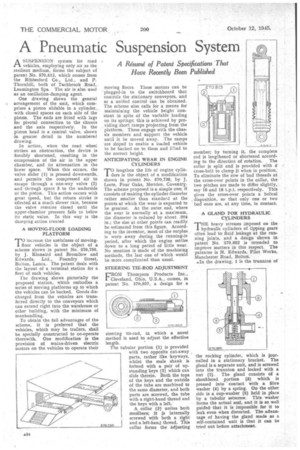
ASUSPENSION system for road vehicles, employing only air as the resilient medium, forms the subject of patent No. 570,813, which comes from the Ribbesford Co., Ltd., and P. Thornhill, both of Tachbrook Road,. Leamington Spa. The air is also used as an oscillation-damping agent.
One drawing shows the general arrangement of the unit, which comprises a piston slidable in a cylinder.., with closed spaces on each side of the piston. The ends are fitted with lugs for pivotal connection to the chassis and the axle respectively. In the piston head is a control valve, shown in greater detail in the numbered &awing.
In action, when the road wheel strikes an obstruction, the device is forcibly shortened, resulting in the compression of the air in the upper chamber, and its attenuation in the lower space. When this occurs, the valve slider (1) is pressed downwards, and permits the compressed air to escape through a one-way valve (2) and through space 3 to the underside of the piston. This action occurs with great speed, but the return stroke is effected at a much slower rate, because the valve remains closed until the upper-chamber pressure falls to below its static value. In this way is the damping action created A MOVING-FLOOR LOADING PLATFORM increase the usefulness of moving floor vehicles is the object of a scheme shown in patent No. 570,750. by J. Kinnaird and Bromilow and Edwards, Ltd., Foundry Street, Bolton, Lancs. The patent deals with the layout of a terminal station for a fleet of such vehicles.
The drawing shows pictorially the proposed station, which embodies a series of moving platforms up to which the vehicles can be backed. Goods discharged from the vehicles are transferred directly to the conveyors which can extend right into the warehouse or other building, with the minimum of manhandling.
To obtain the full advantages of the scheme, it is preferred that the vehicles, which may be trailers, shall be specially constructed to co-operate • therewith. One modification is the provision of mains-driven electric motors on the vehicles to operate their moving floors. These motors can be plugged-in to the switchboard that controls the stationary conveyors, and so a unified control can be obtained. The scheme also calls for a means for maintaining the vehicle height constant in spite of the variable loading on its springs; this is achieved by providing short ramps projecting from the platform. These engage with the chassis members and support the vehicle until it be moved away. The ramps are sloped to enable a loaded vehicle to be backed on to them and listed to the correct height.
ANTICIPATING WEAR IN ENGINE CYLINDERS
TO lengthen the life of engine cylinders is the object of a modification shown in patent No. 574,738, by J. Leete, Four Oaks, Meriden, Coventry. The scheme proposed is a simple one; it consists of making the cylinder diameter rather smaller than standard at the points at which the wear is expected to be greatest. At the outer end, where the wear is normally at a maximum, the diameter is reduced by about .004 in.; the size at other points can readily be estimated from this figure. According to the inventor, most of the surplus is worn away during the running-in period, after which the engine settles down to a long period of little wear. No mention is made of the machining methods, the last one of which would be more complicated than usual.
STEERING TIE-ROD ADJUSTMENT
EIROM Thompson Products Inc., Cleveland, Ohio, U.S.A., comes, in patent No. 570,807. a design for a
steering tie-rod, in which a novel method is used to adjust the effective length. The tubular portion (1) is provided
with two opposite cut-away parts, rather like keyways, whilst the male shank is for`rned with a pair of upstanding keys (2) which can slide therein. Both the tops of the keys and the outside of the tube are machined to the same diameter, and both parts are screwed, the tube with a right-hand thread and the keys with a left.
A collar (3J unites both menibers; it is internally screwed with both a right and a left-hand thread. This collar forms the adjusting member; by turning it, the complete rod is lengthened or shortened according to the direction of rotation. The collar is split and is provided with t cross-bolt to clamp it when in position. To eliminate the row of bad threads at the cross-over points in the collar, the two pitches are made to differ slightly, say 16 and 18 t.p.i. respectively. This gives the cross-over points a helical disposition, so that only one or two bad ones are, at any time, in contact.
A GLAND FOR HYDRAULIC CYLINDERS
THE heavy stresses imposed on the hydraulic cylinders of tipping gears often lead to fluid leakage at the running joints, and a design shown in patent No. 570,882 is intended to improve matters in this respect. The patentee is M. Edwards, Pilot Works. Manchester Road, Bolton.
.In the drawing, 1 is the trunnion of the rocking cylinder, which is jour. nailedin a stationary bracket. The gland is a separate unit, and is screwed into the trunnion and locked with a nut (2). The gland consists of a shouldered portion (3) which is pressed into contact with a fibre washer (4) by a spring. On the other side is a cup-washer (5) held in place by a tubular setscrew. This washer forms the actual seal, and it is so well guided that it is impossible for it to leak even when distorted. The advantage of having the gland made as a self-contained unit is that it can be tried out before attachment.