THE NEW THORNY CROFT SIX-WHEELER.
Page 50

Page 51

Page 52

Page 53

If you've noticed an error in this article please click here to report it so we can fix it.
A New Product which will Handle Loads of from 30 cwt. to 50 cwt. and Move Them Over the Worst of Lands. Interesting Trials on Laffan's Plain.
THOSE of us who have been fortunate enough to obtain facilities for watching rigid-frame six-wheelers under test have thereby had a revelation in transport and have been compelled quickly to alter our views" about the capabilities of motor vehicles. Up to the end of the war the motor vehicle needed the firm highway for its locomotion, just as to-day the tramcar still needs its steel track and the railway train its railroad. The use of creeper tracks enabled the motor vehicle to tackle cross-country stretches, but only at a reduced pace, this loss of speed being very noticeable whenever a hard road was once more encountered.
However, it was realized that war-time experiences had demonstrated the value and proved the applicability of the motor vehicle in undeveloped lands and over trackless areas, and busy minds have been at work on the improvement of the creeper track on the one hand and on the employment of more wheels than four. At one of the War Office demonstrations on Laffan's Plain two years ago the performance of a rigid-frame six-wheeler came as a surprise to those who had not expected that wheeled vehicles could tackle loose, sandy soil and really rough ground. Yet what we saw last week confidently essayed over the same ground and triumphantly accomplished easily put into the shade the attainments of October, 1924.
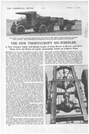
The vehicle we were testing was the latest product of the Thornyeroft works. The type has been in the process of development for some months, undergoing severe trials at the hands of the War Office and of overseas Governments and business interests, and it is new in the stage of regular production. The actual vehicle which we were invited to put to any test we pleased is one of an order for 23 now being supplied to the Government of the Soudan in connection with the cotton-growing industry. It differs from the standard product in a few details. Thus, the chassis is mounted on 40-in. by 8-in, pneumatic tyres, it has acetylene headlamps and a water-cooled tyre inflator, and it hauled a trailer with a test load of a ton,havino itself a test load of 30 cwt. in addition to a substantial body and a considerable equipment. An important item of this equipment was a set of chains for the driving wheels. It seemed to us that the driver was prepared to undertake any task demanded by us ; with perfect sang froid he made a bee-line for each new destination, regardless of the nature of the land, and never troubled to make for a roadway or levelled track. Plunging through heather and over plantations of fir saplings was occasionally the shortest way from one trial ground to another,and it was calmly taken! It seemed that nothing short of a wood or 4 ft. of water need be considered as a hindrance to movement and one became quite exhilarated at what often seemed a risk, but never was!
Photographs, notoriously, rarely do justice to the severity of a test ground. Hence it is not possible pictorially to convey an impression of the seemingly impossible nature of the surface (a courtesy term in this case) of the test hill. It Wag simply a deep, lobse soil of sand, coarse loam and c28
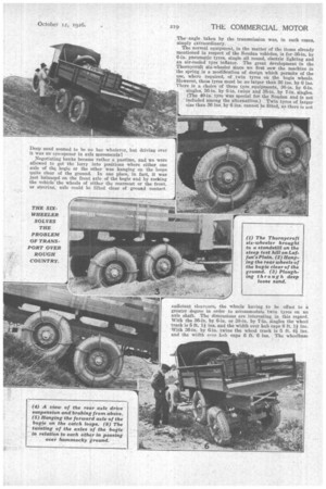
flints, with no cohesion "whatever. It would spin away from the wheels and, being hopelessly irregular, the average gradient of 1 in 31 would• ofteh be 1 in 2 under the driving wheels where the soil had banked up. Yet on this awful surface the lorry, with its 30-cwt. load (but without the trailer), went over without a falter. At a second test it was stopped on the steepest part for a photograph, and we confess we expected to see it slide down backwards on its locked wheels. From this position it restarted and climbed the last few yards without a moment's hesitation.
Deep sand seemed to be 110 bar whatever, but driving over it was an eye-opener in axle movements!
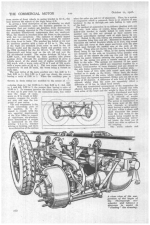
Negotiating banks became rather a pastime, and we were allowed to get the lorry into positions where either one axle of the bogie or the other was hanging on the loops quite clear of the ground. In one place, in fact, it was just balanced on the front axle of the bogie and by rocking the vehicle the wheels of either the rearmost or the front, or steerinz, axle could be lifted clear of ground contact.
sufficient clean:aloe, the wheels having to be • offset to a greater degree in order to accommodate twin tyres on an axle shaft. The dimensions are interesting, in this regard. With the 36-in. by 6-in. or 38-in. by 7-in. iiugles the wheel track is 5 ft. 1 ins, and the width over hub caps 6 ft. 11 ins. With 36-in. by 6-iu, twins the wheel track is 5 ft. g and the width over Inib caps 6 ft. 6 ins. The wheelbase
from centre of front wheels to spring bracket is 12 ft., the base between the wheels of the bogie being 4 ft.
In giving ,a brief description of the six-wheeler we shall practically concentrate upon the features peculiar to it, assuming that our readers are familiar, from descriptions that have already appeared in The Commercial Motor, with the standard Thornycroft components that are employed.
Thus, the chassis is standard from the front to the gearbox, with but two exceptions. The radiator is slightly higher and has an extra row of gilled tubes, making the number five from front to back. The gearbox has bolted at its rear an auxiliary gearbox with a ratio of 2.3 to 1. The axles of the bogie are standard 2-ton axles as used in the A2 (2-ton) model and the engine, clutch and gearbox unit is the FB4 developed for the Al 30-cwt. War Office subsidy Thornycroft and being used on the Al, A2 and now the A3 six-wheeled models. The engine develops 36 b.b.p. at 1,500 r.p.M., and through the main gearbox (the power passing direct through the auxiliary gearbox) it gives a Vehicle speed, at the stated rate of engine revolutions, of 201 m.p.h. with a worm ratio of 71 to 1 and of 18* m.p.h. with a worm ratio of 81 to 1. The two worm wheels have respectively 31 and 35 teeth, the worm being a 4-start in each case.
The gear ratios of the main gearbox are : 1st, 4.45 to 1; 2nd, 2.61 to 1; 3rd, 1.58 to 1 and top direct, the reverse having a ratio of 5.69 to 1. When the auxiliary gear is thrown in these ratios are modified to the extent of — 2.2 reducing them to : 1st, 10.25 to 1; 2nd, 6.02 to 1; 3rd, 3.62 to 1 and 4th, 2.30 to 1, the reverse then having a ratio of 13.09 to 1. In common practice the driver does not attempt The rear suspension is the deeply interesting part of the machine. It is designed to comply with the two essential requirements of the War Office in respect of rigid-frame six-wheelers. Even distribution of weight is maintained on all four driving Wheel s, whether driving or braking, and there is no distortion of the springs when the axles are put out of alignment. Thus, by a system of suspension which is patented, there is an absence of any tendency to;.dig in through ,one axle failing to take part of the load
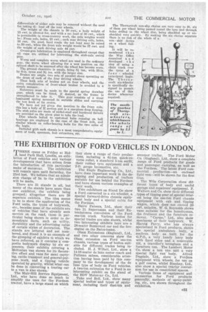
The method of suspension is as follows (dealing with one side only, both sides, of course, being alike) :—A strong hollow-cast bracket is rigidly bolted to each frame side member and on this are pivoted at their centres two inverted semi-elliptic springs each of eight leaves 2* ins. wide. Bolted to the axle casing are trunnion brackets with the trunnion lying fore and aft. Mounted in bushes on the trunnions are swivel brackets which, as it were, ring round the axles and carry at their upper and lower ends the pins which pass through the bushed eyes at the ends of the springs. These pins are 3* ins. long (the eyes, be it remembered, being 21 ins. long). Thus, as the spring anchorages are mounted on the axle on trunnions lying parallel with the axis of the chassis the axle can rise and fall or rock about its centre without twisting the spring, and the end play in the spring eye gives a certain amount of lateral float to the axle. The springs are mounted 13 ins. apart on the spring brackets, which are connected together by a tubular cross-member of large diameter and are stayed to the side frame members by triangulated Ti section steel.
Catch loops of wire cable pass round each axle, being hooked on to studs on the frame. These limit the downward movement, of the axles, whilst rubber buffers on the frame limit the upward movement. Either axle can tilt to an angle of 18 degrees. A difference of axle level of 12 ins, is allowed, whilst when the axles are oppositely tilted a difference of 18 ins, in wheel level occurs. With this symmetrical arrangement of the suspension the effective fulcrum point is brought into a straight line with both axles of the bogie and the weight is then, at all times, equally distributed and there is no tendency for one axle to be relieved of weight under the driving torque. The power is transmitted to -the worm gear of the first axle through a propeller shaft having a spider universal joint, whilst a short, stiff shaft transraitD the power from the first worm to the second, being coupled up by Skefko ball-bearing universal joints, the front one of which can slide on splines in the coupling.
The worm wheels and
differentials of either axle may be removed without the need for taking th, load off the rear wheels.
The weight of the chassis is 50 cwt., a body weight of 15 cwt. is allowed for, and with a net load of 30 cwt., which is permissible in cross-country work, the axle weights would be: Front axle, laden, 23 cwt.; each rear driving axle, laden, 36 cwt. On good, hard roads the net load may be raised to 50 cwt., when the front axle weight would be27 cwt. and the weight of each driving axle 44 cwt Grease-gun lubrication is employed throughout except that oil cups are utilized for lubricating the stub-axle swivel pins.
Worm and complete worm wheel are used in the ordinary gear, the worm wheel allowing for a new position on the splined shaft to be assumed after the wheel has become worn.
The ground clearance is ample, being 81 ins., with 36-in. by 6-in. tyres and 9i ins, with the larger size.
Brakes are ample, two sets of parallel shoes operating on the drum of each of the four driving wheels.
Thus both sets of brakes act on four wheels, and the extra complication of front-wheel brakes is avoided in a simple manner..
Reference must be made to the special spring drawbar gear, which can be fitted, if desired, as the frame is strengthened to take it. This gear consists of a stout laminated spring mounted in suitable slides and carrying the tow hook at its centre.
We have not yet given due mention to the front axle, this has a body of H section and is a one-piece drop forging. The stub axles are made of nickel-steel and hardened thrusts are provided on the pivot pins to take the load.
Die wheels bolted to cast-steel hubs running on ball bearings are employed in the case of the -front axle, and similar wheels on roller-bearing hubs for the two axles of the bogie.
Included yrith each chassis is a most comprehensive equipment of tools, spanners, hub extractors, etc. The Thornycroft non-slip chains are very easy to fit, six of them per wheel being passed round the tyre and through holes drilled in the wheel disc, being shackled up or unshackled very quickly. By making the six chains separate there is no risk of the whole of a non skid device on a wheel failing.
It will be remembered that the War . Office conceived a n d developed t h e idea of using a chain track over the tyres of a I our wheeled twin-tyred bogie. The Thornycroft six-Wheeler is specifically designed to permit the use of this device whenever required.


