


• DESIGNED FOR FAST PASSENGER WORK:
Page 47
Page 48
Page 49
If you've noticed an error in this article please click here to report it so we can fix it.
The New Light Low-level Bristol has Raked and Offset Drive, Servooperated Brakes and a Highly Efficient Power Unit.
AN exclusive description of the latest Bristol passenger chassis, which is known as the-low-loading type B, was published in the issue of this journal dated June 15th. We have been following with interest the design and construction of this chassis since the previous • October, and now that some of these vehicles are actually in service we are permitted to give further details and illustrations of what is certainly one of the most practicable " and interesting types of four-wheeled passenger chassis with which we have dealt.
It is intended for 32-seater, singledeck buses, and has a frame height of 2 ft. 1 in. In the latest type of body the floor is not more than 13 ins, above this, So that the maximum platform level theit comes to 2 ft. 21 ins. Unladen, • the chassis weighs 2 tons 16 cwt., and it is important •to note that it is nearly .half a ton lighter than its prototype, the Bristol 4-tonner. The improved method of body construction has per-• mitted a further saving of 'nearly half a ton in the body alone, so that the total reduction effected is of the greatest importance, and yet nowhere has this weight been saved at the expense of reliability and strength.
So far as possible, standardBristol components have been employed, although the units themselves have naturally been greatly modified. To permit a generous size of final-drive casing without. interfering with the passage-way between the seats, the whole drive line, including the engine, has been offset to the extent of 2 degrees 46 mins., thusbringing the axle casing close to the near-side rearwheel arch, where it comes under the back-to-back seats and thus does not interfere with the comfort of passengers.
The worm is situated under the worm, wheel, and to avoid excessive angles in the drive the engine is tilted to the extent of 4 degrees 7 rains.
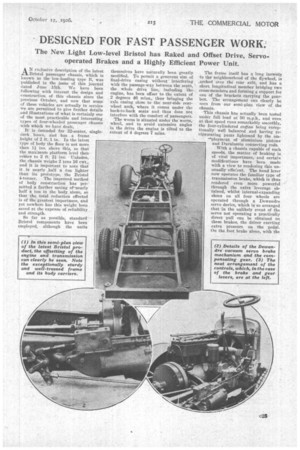
The frame itself has a long inswCUp to theneighbourhood of the flywheel, is arched over the rear axle, and Ims a short longitudinal member bridging two cress-members and forming a support for one of the brackets carrying the gearbox. The arrangement can clearly be seen from our semi-plan view of the chassis.
This chassis has actually 'been tested wider lull load at 50 m.p.h„ and even at that speed runs remarkably smoothly, the four-cylindered engine being exCeptionally well balanced and having reciprocating par' lightened by the, em
-^ployment of aluminium pistons and Duralumin connecting reds.
With a chassis capable of such speeds, the matter of braking is of vital importance, and certain modifications have been made with a view to rendering this unusually efficient. The hand lever now operates the familiar type of tranSmission brake, which is thus rendered even more powerful through the extra leverage obtained, whilst internal-expanding shoes on all four wheels are operated through. a Dewandre servo device, which is so arranged that in the unlikely event of the servo not operating a practically direct pull can be obtained on these brakes, the driver exerting extra pressure on the pedal. On the foot brake alone, with the
Derv° in operation and with a total weight of 9tons, the chassis has been pulled up in 75 ft. from ,a speed of 30 m.p.h., whilst with the foot brake alone, without the servo, the stopping distance was 13 ft. from 12 m.p.h.
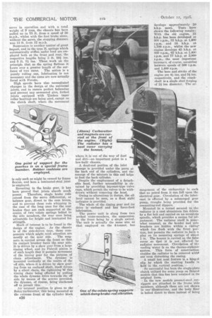
Suspension is another matter of great import, and in the type B, springs which automatically stiffen under load are employed both at the front and rear, the respective lengths being 3 ft. 101 and 5 ft. Di ins. These work on the principle that as the spring flattens it hears over a greater length of the surfaces of two cams. The action is a purely rolling one, lubrication is not necessary and the cams are now actually faced with Ferodo.
High speeds have also necessitated changes in the design of the universal joints, and to ensure perfect balancing and prevent any unwanted give, forked joints equipped with Timken taper roller bearings are being used, except on the clutch shaft, where the movement is only such as might be caused by frame flexion, and here a laminated-steel joint is employed.
Reverting to the brake gear, it has been proved that joints absorb much power. Therefore, single brake rods extend from the servo differential, or balance gear, direct to the cam levers, and to prevent these rods whipping in the case of the long ones for the rear brakes they are each supported at the centre of two volute springs bolted to the side members, the rear ones being adjustable for height and laminated for strength. Much of interest is to be found in the design of the engine. As the chassis is of the side-driven type, those components which might need attention are
mostly at the near side. The magneto is. carried across the front so that its contact breaker faces the near side. It is driven by a skew gear from a large timing wlieel, and its Fabroil pinion is of such length that it permits movement of the timing gear for the purpose of chain adjustment. The dynamo is mounted vertically at the centre of the off side, where it is driven by skew gearing from an encloeed shaft, itself driven by a silent chain, the tightening 'bf this timing chain being effected by pulling the whole dynamo drive towards the off side by means of the screws provided, the dynamo, of course, being slackened off to permit this.
An unusual position is given to the &lex carburetter,' this being mounted at the extreme front of the cylinder block e26 where it is out of the way of dust and dirt—an important point in a low-built chassis.
A dead-end portion of the inlet passage is provided under the ports at the back end of the cylinders, and the resurge of the mixture in this end helps to feed the back cylinder.
Despite the employment of a detachable head, further accessibility is obtained by providing bayonet-type valve caps, which permit the valves to be withdrawn without removing the head.
Owing to alterations in design, the oil level cannot be seen, so a float sight indicator is provided.
The whole of the timing gear and its drive is enclosed and has force-feed lubrication.
The power unit is slung from two arched cross-members, the suspension in the front being by a single swivel. The unit is actually the same size as that employed on the 4-tonner, but
develops approximately 20 b.h.p. more. Tests have shown the following results: With the old engine, 33 b.h.p. has been developed at 800 r.p.m., 52 b.h.p. at 1,400 r.p.m. and 55 b.h.p. at 1,700 r.p.m., whilst the new engine develops 43 b.h.p. at 800 r.p.m., 65 b.h.p. at 1,400 r.p.m. and 77 b.h.p. at 2,000 r.p.m., the most important increases, of course, occurring between speeds of 800 r.p.m. and 1,400 r.p.m.
The bore and stroke of the engine are 44 ins. and 5i respectively, and the crankshaft is a single steel forging of 2-ir ins diameter. The ar rangement of the carbueetter is such that no petrol from it can fall upon the electrical gear. Circulation of the lubricant is effected by a submerged gear pump, troughs being provided for the connecting-rod dippers.
Mounted in a tunnel secured to the radiator is a cast aluminium fan driven by a flat belt and carried on an eccentric spindle, which provides a means for adjustment. The radiator itself is somewhat unusual, as the header and side brackets are bidden within a casing which lies flush with the front portion, but permits the radiator to have a play on its mounting springs of about: 1 in. The bonnet is carried on the false cover so tbat it is not affected by radiator movement. Circulation of the cooling water is on the thermo-siphonie system. This form of construction enables the radiator to be removed withil out even disturbing the casing.
A. small but neat feature is a hinged clip by which the starting handl& is held in the vertical position.
So successful has been the single-plate clutch utilized for some years on, Bristol models that this has been retained in its original form. In the new models pressed-steel outriggers are attached to the frame 'side members, although these are not shown in our illustrations, and the body floor is bolted direct to these instead of being carried on rubber buffers as formerly, so, to prevent gearbox noises and vibrations from being transmitted to the body from the chassis, the gearbox is three-point mounted upon upper and lower cushions of tough rubber, thus there is no direct mechanical connection between it and the frame, except through the shafts and controls. The chassis can, of course, be sold equipped with rubberbuffer mountings on the frame, as in the ease of the larger model, if desired, in which event the body is really doubly insulated, The gearbox provides four speeds and a reverse, and is equipped with the Bristol patent control system. This requires only one sliding and rockihg shaft, which is connected to the changespeed lever through the medium of a eardan shaft. This presents the additional advantage that the offsetting of the gearbox does not cause any extra complication. The gearbox shafts are mounted on ball and roller bearings, and the gear teeth are all ground to ensure correct meshing and silence.
A tube 3 ins. in diameter is employed for the propeller shaft. • The rear axle 'itself has a cast-steel case, tubes of nickel-chrome steel and roller bearings for the road wheels, all ' the hubs having labrynth water. excluders. The brake-shoe anchorages are much stiffer than formerly, to bear the extra stresses of servo braking, and the shoes themselves are easily adjustable in situ by bronze nuts with ball snicks, following the usual Bristol method. The drums are of 174 his: internal diameter and 6 ins, face width. It is notable that the front-wheel brakes may be omitted if not required.
A nickel-chrome stamping is employed for the front axle, the stub axles and steering arms being of the same material.
Disc wheels with 34-in.
by straight sided pneumatic tyres are used all round, those at the rear being twins.
The fuel tank is carried below the body on the off side, being attached by means of three mild-steel strap s. The filler is accessibly situated o n t side the body and the total capacity is 30 gallons.
s. Choice is given of two axle ratios to 1 and 6 to 1, and with the engine running at 2,000 np.m. the corresponding speeds at the following gearbox ratios are: top, 1 to 1 (40 m.p.h., 34 m.p.h.) ; first, 1.66 to 1 (22.5 m.p.h:, 20 m.p.h.) ; second, 3.125 to 1 (12.8 m.p.h.. 11 m.p.h.) ; first, 6.25 to 1 (6.4 m.p.h., 5 m.p.h.) ; reverse, 3.94 to 1 (10.1 m.p.h., 9 m.p.h.).
The main ,dimensions are; overall length, 25 ft.; length behind driver's seat, 20 ft.; overall width, 7 ft.; • wheelbase, 15 ft. 7 ins. •, track, (front)' 6 ft. in., (rear) 5 ft. 8i ins.; turning circle, 58 ft. 6 ins.
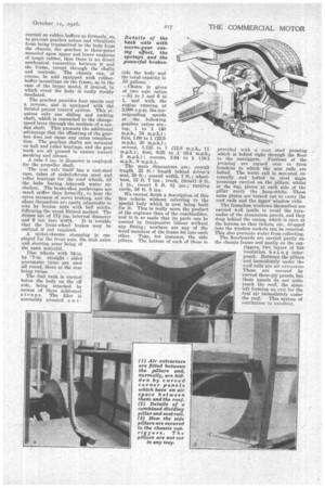
We cannot finish a description of this fine vehicle without referring to the special body which is now being built for it. This is really more the product of the engineer than of the coachbuilder, and it is so made that its parts can be erected by inexpensive labour without any fitting ;• nowhere are any of the wood members of the frame let into each other. Take, for instance, the side pillars. The bottom of each of these is
provided with a neat steel pressing which is bolted right through the floor to the outriggers. Portions of the pressing are turned over to form brackets to which the seat rails are bolted. The waist rail is mounted, externally and bolted to, steel angle pressings carried on the pillars, whilst at the top, plates at each side of the pillar carry the hoop-sticks. These same plates are turned out to tarry the roof rails and the upper window rails.
The frameless windows themselves are carried well inside to avoid the turnunder of the aluminium panels, and they drop behind the casing, which is open at the bottom so that tickets, etc., dropped into the window sockets can be removed. This also prevents water from collecting.
The floorboards are carried partly on the chassis frame and partly on the outriggers, two layers of felt insulation being interposed. Between the pillars and immediately under the roof rails are air extractors These are covered by curved three-ply panels, but these panels do not quite reach the roof, the space left forming an exit for the foul air immediately under the roof. This system of ventilation is excellent.