


Patents Completed.
Page 24
If you've noticed an error in this article please click here to report it so we can fix it.
Pneumatic Hubs for Wheels. Detachable Rim Adjustment. Electrical Engine Starting Device.
Copies of complete specifications of the patents published on this page can be obtained from the Sales Branch, Patent Office, Holborn, W.C., at the cost of sixpence for each specification.
JOSE GREPPI AND ANTONIO ROISIANACH, NO. 101,177, dated 9th March, 1916.—This invention applies the pneumatic device to the hub instead of to the rim of a vehicle wheel. A solid rubber tire is shown in the cross-section drawing, but an iron or other tire may be used. An annular space is formed at the hub between a flanged casing to which the inner ends of the spokes are attached and a flanged bush for mounting on the axle. Rubber cushioning devices are placed at each end of this annular space with an air chamber between. Under load this annular space would assume an eccentric form.
F. W. BAKER, No. 12,227, dated 25th August, 1915.—The first drawing shows a view of the mechanism partly in section as seen looking from the hub to the inside of the rim ; the second drawing is a cross-section, each half of which is taken at a different point in the rim circumference.
The detaching mechanism is mounted in a fixed rim, which has a fixed flange at one side and a slotted part to receive a collapsible flange at the other. The outer or tire-holding rim consists of two flanged rings which in cross-section are movable in scissors fashion. The collapsible flange is a split ring, the ends of which are jointed to toggle levers.
In the first drawing the travelling nut of the toggles is in the position which contracts the split ring, expanding the tire flanges and allowing the tire, or rim and tire, to be withdrawn. When the rim and tire are replaced the cross-bolt is rotated, and the ring, or collapsible flange, is expanded to the position shown in the right half of the second drawing forcing the two halves of the detachable rim into working position. The left half of the second illustration shows a pivoted lever which forces the detachable rim, after it, is loosened, off the permanent rim.
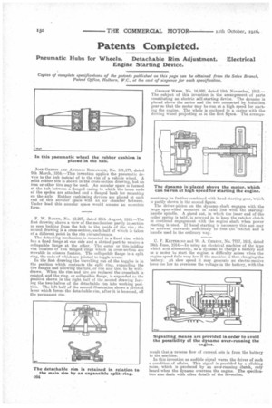
Gaol= WEI3B, No. 16,080, dated 15th November, 1915.— The subject of this invention is the arrangement of parts constituting an electric self-starting device. The dynamo is placed above the motor and the two connected by reduction gear so that the motor may be run at, a high speed for starting the engine. The whole is enclosed in a casing with the driving wheel projecting as in the first figure. The arrange ment may be further combined with hand-starting gear, -which is partly shown in the second figure. The driver-pinion on the dynamo shaft engages with the large spur-wheel mounted in axial line with the startinghandle spindle. A gland nut, in which the inner end of the coiled spring is held, is screwed in to keep the ratchet clutch in continual engagement with the engine shaft when power starting is used. If hand starting is necessary this nut may be screwed outwards sufficiently to free the ratchet and a handle used in the ordinary way.
C. F. KETTERING and W. A. CHRYST, No. 7757, 1915, dated 24th June, 1914.—In using an electrical machine of the type which acts alternately, as a dynamo to charge a battery and as a motor to start the engine, a difficulty arises when the engine speed falls very low if the machine is then charging the battery. At slow speed it may generate an electro-motive force too low to overcome the voltage in the battery, with the
result that a reverse flow of current sets in from the battery to the machine.
In this invention an audible signal warns the driver of such a condition of affairs. This signal is provided by a clicking noise, which is produced by an over-running clutch, only heard when the dynamo overruns the engine. The specification also deals with other details of the invention.