A Torque-damping Device
Page 68

If you've noticed an error in this article please click here to report it so we can fix it.
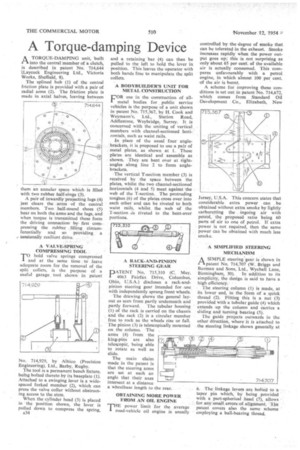
A TORQUE-DAMPING unit, built 1-1 into the central member of a Chitch, is described in patent No. 7.14,644 '(Layeock Engineering Ltd., Victoria Works, Sheffield, 8).
The splined hub (1) of the central friction plate is provided with a pair of radial arms (2). The friction plate is made in axial halves, leaving between
them an annular space which is filled with two -rubber half4ings (3).
A pair of inwardly projecting lugs (4) just clears the arms of the central members. Two half-round shoes (5) bear on both the arms and the lugs, and when torque is transmitted these form the driving connection by first compressing the rubber filling circumferentially and so providing a , torsionally resilient drive.
A VALVE-SPRING COMPRESSING TOOL
TO hold valve spring compressed and at the same time to leave adequate room for the removal of the split collets, is the purpose of a useful garage. tool shown in patent
No. 714,929, by Albico (Precision Engineering), Ltd., Barby, Rugby.
The tool is a permanent bench fixture, being bolted thereto by its baseplate (I). Attached to a swinging lever is a widespaced forked member (2), which can press the valve collar without obstructing access to the stem.
When the cylinder head (3) is placed in the position shown, the lever is pulled down to compress the spring, A34 and a retaining bar (4) can then be pulled to the left to hold the lever in position. This leaves the operator with both hands free to manipulate the split collets.
A BODYBUILDER'S UNIT FOR METAL CONSTRUCHON
rOR use in the construction of all
metal bodies for public service vehicles is the purpose of a unit shown in patent No. 715,367, by H. Cook and Weymanhs, Ltd., Station Road, Addlestone, Weybridge, Surrey. It is concerned with the uniting of vertical members with channel-sectioned horizontals, such as waist rails.
In place of the usual four anglebrackets, it is proposed to use a pair of , metal plates, as shown at I. These plates are identical and assemble as shown. They are bent over at rightangles along line 2 to form anglebrackets.
The vertical T-section member (3) is received by the space between the plates, whilst the•two channel-sectioned horizontals (4 and 5) meet against the web of the T-section. The protruding tongues (6) of the plates cross over into each other and can be riveted to both waist rails, whilst the web of the T-section -is riveted to the bent-over portions.
A RACK-AND-PINION STEERING GEAR IIDATENT No. 715,310 (C. May, I 4063 Fairfax Drive, Columbus, Ohio, U.S.A.) discloses a rack-andpinion steering gear intended for -use with independently sprung front wheels.
The drawing shows the general layout as seen from partly underneath and partly forward. The tubular housing (1) of the rack is carried on the chassis and the rack (2) is a circular member free to rock as the wheels rise or fall. The pinion (3) is telescopically mounted on the column. The arms (a) from the king-pins are also telescopic, being able to rotate as well as slide The main claim made in the patent is that the steering arms are set at such an angle that their axes intersect at a distance a wheelbase length to the rear.
OBTAINING MORE POWER FROM AN OIL ENGINE power limit for the average road-vehicle oil engine is usually controlled by the degree of smoke that can be tolerated in the exhaust. Smoke increases rapidly when the power output goes up; this is not surprising as only about 65 per cent. of the available air is actually consumed. This compares unfavourably with a petrol engine, in which almost 100 per cent. of the air is burnt.
A scheme for improving these conditions is set out in patent No. 714,672, which comes from Standard Oil Development Co., Elizabeth, New Jersey, U.S.A. Th's concern states that considerable extra power can . be obtained without extra smoke by lightly carburetting the ingoing air with petrol, the proposed ratio being 60 parts of air to one of petrol. If extra power is not required, then the same power can be obtained with much less smoke.
A SIMPLIFIED STEERING MECHANISM
ASIMPLE steering gear is shown in patent No. 714,707 (W. Briggs and Burman and Sons, Ltd., Wychall Lane, Birmingham, 30). In addition to its simplicity, the design is said to have a high efficiency.
The steering column (1) is made, at its lower end, in the form of a quick thread (2). Fitting this is a nut (3) provided with a tubular guide (4) which extends up the column and carries a sliding and turning bearing (5).
The guide projects outwards in the other direction, where it is attached to the steering linkage shown generally, at 6. The linkage levers are bolted to a taper pin which, by being provided with a part-spherical head (7), allows for any small errorsof aljgument. The patent covers also the same scheme employing a ball-bearing thread.


