A Dual-pressure Hydraulic-braking System
Page 40

If you've noticed an error in this article please click here to report it so we can fix it.
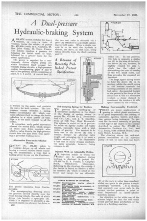
ABRAKE system suitable for heavy vehicles, or even, a train of vehicles, forms the subject of patent No. 472,620 (void) by L. Coatalen, 27, Rue Jules Verne, St. Ouen, France. The scheme employs a pressure for bringing the brake shoes to bear, followed by a greater force .for the actual application.
The power is supplied by a continuously driven duplex pump (7) which circulates fluid around two separate piping circuits, a high-pressure system incorporating. pipes 1 and 9 and a low-pressure circuit consisting of pipes, 6, 4, 1 and 8. • A control box (2) is worked by the pedal, and contains the valve for both systems. The lowpressure circuit includes a • springloaded accumulator (5) which contains sufficient fluid to charge the brake cylinders in •a short period of time. Pipe 3 is the main conduit to all the brakes.
In operation, early pedal movement releases the stored fluid, which presses all shoes into drum contact, after which a valve diverts the high-pressure circuit into the pipe lines, thus applying a powerful braking force.
Alternative Four-or-six-wheeled Chassis.
DA.TENT No. 472,461 refers to 1 vehicles driven on all wheels and having a central tubular frame enclosing the transmission, a type that is finding great favour on the Continent The patent slovakia.
The accompanying drawing shows the gearbox carried directly over the front driving wheels, the axle of which drives (via bevels) a spur-gear (2). When it is required to assemble a sixwheeled chassis (as shown) the drive to B56 Self-damping Spring for Trailers.
Rprevent the building-up of nwanted oscillations is the object • of the design of spring shown in patent No. 472,393 by J. Brockhouse and Co., Ltd., and j. T. Smerdon, both of Hill Top, West Bromwich. The scheme is stated to be of particular value on lightly loaded yet bulky trailers, especially those with a high centre of gravity. The method is to form one of the leaves (2) into a friction damper by allowing extra length and arranging for it to meet a friction surface (1). The illustration is but one of many designs disclosed, the same principle, however, being common to all.
Injector With an Adjustable Orifice.
AN injectionnozzle in which the orifice can be adjusted during working is disclosed in patent No. 472,625 by E. A. Franks, 5, Caegwyn Road, Whitchurch, Glamorgan. Referring to the drawing, the casing cf the device is bored to receive a tubular member (4) which is blind at the lower end except for an off-centre
orifice (2). In one position, this hole is opposite a similar one (3) in the nose of the body; the sleeve (4) can, however, be slightly rotated by arm 1, which has the effect of diminishing the area of overlap of the two small bores, and thus provides the required adjustment. The large upper spring serves to hold the sleeve (4) on 'its seating, whilst the small spring at the bottom controls the opening pressure of the central ball-valve. An essential feature of the patent is the shape of the small bore 3; this is a miniature venturi, a shape claimed to counteract the tendency to side spray caused by the overlap.
Making Gear-assembly Foolproof.
THERE are many applications of
gearing in which phase relationship is of great importance, the driving of camshafts, ignition timers, and injection pumps being instances. To prevent the incorrect assembly of gearing of this type is the object of the scheme described in patent No. 471,575 by Automotive Products Co., Ltd., and G. J. Trapp, both of Brock House, Laugh= Street, London, W.1.
The dra.wing shows the rack-andpinion mechanism of an injection pump ; it will he seen that one tooth (I) of the rack is wider than standard, whilst one space in the pinion is correspondingly increased. . It is obvious that assembly can occur only in the correct relative position, a point of vital importance in multi-cylinder injection pumps.
An objection to the wider use of the scheme might be that the odd tooth would prevent mass production of the gears on a hobbing machine.


