 1
1 2
2 3
3 4
4 5
5 6
6 7
7 8
8 9
9 10
10 11
11 12
12 13
13 14
14 15
15 16
16 17
17 18
18 19
19 20
20 21
21 22
22 23
23 24
24 25
25 26
26 27
27 28
28 29
29 30
30 31
31 32
32 33
33 34
34 35
35 36
36 37
37 38
38 39
39 40
40 41
41 42
42 43
43 44
44 45
45 46
46 47
47 48
48 49
49 50
50 51
51 52
52 53
53 54
54 55
55 56
56 57
57 58
58 59
59 60
60 61
61 62
62 63
63 64
64 65
65 66
66 67
67 68
68 69
69 70
70 71
71 72
72 73
73 74
74 75
75 76
76 77
77 78
78 79
79 80
80 81
81 82
82 83
83 84
84 85
85 86
86 87
87 88
88 89
89 90
90 91
91 92
92 93
93 94
94 95
95 96
96 97
97 98
98 99
99 100
100 101
101 102
102 103
103 104
104 105
105 106
106 107
107 108
108 109
109 110
110 111
111 112
112 113
113 114
114 115
115 116
116 117
117 118
118 119
119 120
120 121
121 122
122 123
123 124
124 125
125 126
126 127
127 128
128 129
129 130
130 131
131 132
132 133
133 134
134 135
135 136
136 137
137 138
138 139
139 140
140 141
141 142
142 143
143 144
144 145
145 146
146 147
147 148
148 149
149 150
150 151
151 152
152 153
153 154
154 155
155 156
156 157
157 158
158 159
159 160
160 161
161 162
162 163
163 164
164 165
165 166
166 167
167 168
168 169
169 170
170 171
171 172
172 173
173 174
174 175
175 176
176 177
177 178
178 179
179 180
180 181
181 182
182 183
183 184
184 185
185 186
186 187
187 188
188 189
189 190
190 191
191 192
192 193
193 194
194 195
195 196
196 197
197 198
198 199
199 200
200 201
201 202
202 203
203 204
204 205
205 206
206 207
207 208
208 209
209 210
210 211
211 212
212 213
213 214
214 215
215 216
216 217
217 218
218 219
219 220
220 221
221 222
222 223
223 224
224 225
225 226
226 227
227 228
228 229
229 230
230 231
231 232
232 233
233 234
234 235
235 236
236 237
237 238
238 239
239 240
240 241
241 242
242 243
243 244
244 245
245 246
246 247
247 248
248 249
249 250
250 251
251 252
252 253
253 254
254 255
255 256
256 257
257 258
258 259
259 260
260 261
261 262
262 263
263 264
264 265
265 266
266 267
267 268
268 269
269 270
270 271
271 272
272 273
273 274
274 275
275 276
276 277
277 278
278 279
279 280
280 281
281 282
282 283
283 284
284 285
285 286
286 287
287 288
288 289
289 290
290 291
291 292
292 293
293 294
294 295
295 296
296 297
297 298
298 299
299 300
300 301
301 302
302 303
303 304
304 305
305 306
306 307
307 308
308 309
309 310
310 311
311 312
312 313
313 314
314 315
315 316
316 317
317 318
318 319
319 320
320 321
321 322
322 323
323 324
324 325
325 326
326 327
327 328
328 THE 100-TONNER Ready for the Road
Page 204
Page 205
If you've noticed an error in this article please click here to report it so we can fix it.
Details of the Remarkable Scammell Articulated 14wheeler, the Construction of which was Forecast by Us Six Months Ago.
RFADERS will remember that in our issue dated May 14th we gave extracts from a speech made by Mr. F. C. Marston, of MRS., Ltd. (formerly Marstons Road Services, Ltd.)., of Liverpool; dealing with an articulated 14-wheeled machine which was being constructed for that company's special purposes and which would carry 100-ton loads. The machine has been built at the Watford works of Scammell Lorries, Ltd., and last Wednesday it underwent its first trials.. Perhaps the most remarkable feature about it is that, whilst the gross laden weight is so tremendous, the weight per square inch of contact between the solid-rubber tyres and the road surface is no more than with any
normal goods-carrying road vehicle. Indeed, the engine is the 80 b.h.p. overhead-valve four-cylindered model of 5-in.; bora and 5i-in stroke that is fitted in the Seammell El-ton four-wheeler and the larger rigid and articulated multiwheelers.
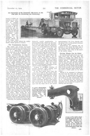
The machine consists of a Motive unit having an ordinarytwci-wheeled *front axle with semi-elliptic springs; Ackerman steering and two oscillating driving axles, parrying tour twin-tyred road wheels in line, and a load-carrying unit, or carrier, having a straight frame built with box-girder side-members pin-bolted at the frontto a swan-neck structure which rests on a spherical bearing on the turntable of the motive unit. For the present two carriers have been constructed, one intended for 05-ton loads and having four wheels in line at the rear, and the other intended for 100-ton loads and having a rear bogie of eight Wheels in two lines.
The motive unit has a frame built up with riveted steelplates, thefonr driving
wheels of which are carried on two short axles, • these being free to oscillate upon longitudinal lever s, trunnionmounted at the forward end and supporting the frame at the rear end through the medium of large cylindrical rubber blocks. These constitute the only t springing of the driving wheels, the recoil being taken by two coil springs behind the rubber blocks, which operate in tension.
The Transmission System.
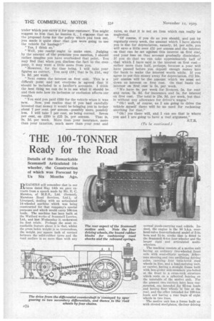
The engine and normal four-speed gearbox are carried in a sub-frame, from which the drive is taken by spiral-bevel gear to a differential countershaft. From each end of the countershaft the Dower is transmitted through spur gearing (incorporating a two-ratio variable gear) to a secondary differential, from 'which it is conveyed to the road wheels 'by two single-roller chains. The total tractive effort in the final stage is thus divided between four chains. Eight forward-gear ratios are provided, the secondary .gear change being controlled by a lever in the cab.
.Dealing.now with the trailing wheels of the carrier, in the case of the 05-tonner a forged-steel cross-member carries two rearward-projecting trunnions, en each of-which is mounted a pair of
wheels on an , axle. These axles are free to swive on a vertical axis, so that they can be steered through a screw-and-nut gear, turned by a large hand wheelwhich is under the control of a man riding on a platform at the rear, end of the machine. In the case of the 100-tonner, four more wheels on two short oscillating axles are fitted to the front ends of the trunnion forgings, these forgings being then allowed to oscillate on the centrally disposed crossmember, thus forming two four-wheeled bogies, each supporting one side of the main frame. They divide the load equally and are free to conform to the camber of the road. The steering of the rearmost wheels is still possible with the 100-tormer, the forward line being fixed.
Naturally, the question of brakinebas demanded careful consideration. A transmission brake, which has the benefit of the very -low gear and, therefore, calls for, little effort, can be operated by a pedal or. a small hand lever, the latter being useful when re-starting the machine on a hill. It is claimed that, without any great effort, the driver can hold the vehicle with this hand lever on a 1-in-10 gradient. There is also a handoperated screw brake which affects the driving -wheels; in addition, all the wheels of the carrier have internal-expanding brakes, these being actuated through a band wheel by the man riding on the rear platform. This man is kept in communication with the driver through a loud-speaking telephone of the Alfred Graham Admiralty type.
Needless to sayVthe -question of ground clearance when passing over small bridges is a difficult one.
It has been stated above that the swan-neck is held to the carrier frame by two pivot pins and it should be added that adjustable hydraulic-ram struts connect the swan-neck structure to the carrier frame. By operating a large double-cylindered, flywheel hand pump, these, struts may be extended, causing the swan-neck to -turn about the pins and raise the front end of the carrier
approximately 1 ft. 3 ins., thereby adding about 8 ins, to the ground clearance at the frame centre.
Alternatively, by releasing the oil pressure in the 'struts the front end of the carrier may be lowered about 1 ft., this causing a 6-in, drop in the centre of the carrier frame.
Driving Wheels Can be Lifted.
On the hydraulic-ram screws are jack nuts which take the load when the vehicle is running and which can be revolved by ratchet spanners to give a pulling action. Should the driving wheels sink into soft ground, sleepers may be placed under the front end of the carrier frame and by means of tbe ratchets the driving wheels may be lifted clear of the ground, to be replaced after the surface has been made good by laying down a boiler plate or by other means.
Should it be necessary to dismount the load from the front end, the swanneck may be disconnected and drawn away, after putting a pair of wheels on the ends of an axle permanently fixed to it. Alternatively, and without the use of any loose jacks, the rear-wheel assembly may be removed to permit unloading from the back.