 1
1 2
2 3
3 4
4 5
5 6
6 7
7 8
8 9
9 10
10 11
11 12
12 13
13 14
14 15
15 16
16 17
17 18
18 19
19 20
20 21
21 22
22 23
23 24
24 25
25 26
26 27
27 28
28 29
29 30
30 31
31 32
32 33
33 34
34 35
35 36
36 37
37 38
38 39
39 40
40 41
41 42
42 43
43 44
44 45
45 46
46 47
47 48
48 49
49 50
50 51
51 52
52 53
53 54
54 55
55 56
56 57
57 58
58 59
59 60
60 61
61 62
62 63
63 64
64 65
65 66
66 67
67 68
68 69
69 70
70 71
71 72
72 73
73 74
74 75
75 76
76 77
77 78
78 79
79 80
80 81
81 82
82 83
83 84
84 85
85 86
86 87
87 88
88 89
89 90
90 91
91 92
92 93
93 94
94 95
95 96
96 97
97 98
98 99
99 100
100 101
101 102
102 103
103 104
104 105
105 106
106 107
107 108
108 109
109 110
110 111
111 112
112 113
113 114
114 115
115 116
116 117
117 118
118 119
119 120
120 121
121 122
122 123
123 124
124 125
125 126
126 127
127 128
128 129
129 130
130 131
131 132
132 133
133 134
134 135
135 136
136 137
137 138
138 139
139 140
140 141
141 142
142 143
143 144
144 145
145 146
146 147
147 148
148 149
149 150
150 151
151 152
152 153
153 154
154 155
155 156
156 157
157 158
158 159
159 160
160 161
161 162
162 163
163 164
164 165
165 166
166 167
167 168
168 169
169 170
170 171
171 172
172 173
173 174
174 175
175 176
176 177
177 178
178 179
179 180
180 181
181 182
182 183
183 184
184 185
185 186
186 187
187 188
188 189
189 190
190 191
191 192
192 193
193 194
194 195
195 196
196 197
197 198
198 199
199 200
200 201
201 202
202 203
203 204
204 205
205 206
206 207
207 208
208 road and workshop
Page 90
Page 91
If you've noticed an error in this article please click here to report it so we can fix it.
by Handyman
Auto-electrics for the mechanic (19)
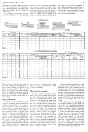
IN dealing with the ignition side of autoelectrics, we have to take into account a necessary increase in voltage from the electrical system, to provide the spark needed to jump a gap inside the distributor and across the spark plug to ignite the fuel /air mixture in the cylinder(s).
In earlier days, the magneto provided this high voltage, but in the magneto we had what amounted to a complete generator, which was quite an expensive item with its own occasional fits of misbehaviour; also it had to be rotated by an external drive from the engine. Today the coil and contact breaker do the same job just as efficiently, far less expensively, and also a good deal more simply.
The voltage needed to cause a spark to leap the rotor arm and plug gaps has to be quite high, usually at least 20,000V and quite often around 25,000V and this has to be obtained or converted from the 6 or 12V output of the battery. The spark generated has to be capable of igniting a petrol /air mixture and needs to be a snappy blue flash, rather than the slower, fat red flame of a lower voltage.
Low tension coil To obtain such a spark from the lower voltage of the battery, two coil windings are needed, one which is known as the primary or low tension coil, and is a winding of comparatively few turns, the second coil which is the high tension winding and has a large number of turns. As current flows through the primary coil, a field is built up around it; this field also envelopes the secondary or high tension coil. If the flow of primary current is interrupted by breaking• the primary circuit, the magnetic field around the two coils will collapse and in the rapid change of the field linking the turns of the secondary coil induces a voltage in each turn of the coil, which, since it has many turns, results in a high secondary voltage. This is the voltage needed to cause a spark to jump the plug gap.
Mechanically arranged To achieve all this and arrange that the spark occurs at the correct piston position on the firing/compression stroke, things have to be arranged mechanically. First, however, I must explain the setup of the coil a little more clearly. The normal coil has two connections for the current on the low tension side and one central connection for the high tension current to be delivered to rotor and plugs. The primary coil winding is fed via the terminal marked S.W. which we take as switch, and continues internally to the terminal marked C.B. or contact breaker. Inside the coil casing one end of the secondary coil is attached to a point on the primary winding wire, just after the coil itself, the other leg of the secondary coil comes out at the central terminal in the insulated cap of the coil. This is usually a screw or plug-in connection and as a rule today, is well water-proofed. The high voltage now induced will cause a spark to leap across the rotor arm to the appropriate plug lead connection in the distributor cap and on to the plug. The contact breaker is in fact a mechanically operated switch which opens and closes the circuit through the primary coil, and is so arranged to form a timed operation that is synchronized with an exact piston position, usually a few degrees before top dead centre.
This setting varies with engine design and the intended purpose of the engine, i.e. whether it is a slow plodding industrial plant engine, or a high performance racing engine capable of turning at 10,000 revs per minute or more. The actual make and break switch is a pair of spring-loaded contact points, operated by a cam with a lobe for each cylinder. The cam is operated by a drive shaft normally geared to the engine camshaft. The contact points themselves have only a short movement, normally not less than 0.012in. and not exceeding 0.016in. This clearance or gap is quite critical, and good performance relies upon the maker's settings being maintained.