


A New Ford Suspension System
Page 60
If you've noticed an error in this article please click here to report it so we can fix it.
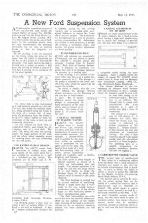
AN independent suspension system of the parallel-link type forms the subject matter of patent No. 634,746, which comes from the Ford Motor Co., Ltd., 88, Regent Street, London, W.I. The chief novelty lies in the use of balljoints for the outermost pivots; these not only accommodate the springing movement but act also as steering piyots, Si' that no king-pins are required.
In the drawing, a bar (1) mounted on the frame forms the pivot of the upper link (2) which is journallecl on the bar at two points in a fore-and-aft direction. The .outer end of the link is formed into a socket to receive a ball joint, the tail-end of which is seen at 3. The ball is carried on an extension (4) of the wheel spindle.
The lower link is also ball-jointed at 5, and similarly pivoted on a bar (6). This bar also forms the resilient member, being extended along the frame in the form of a torsion rod. A nosepece (7) projecting from the frame is fitted with rubber buffers to limit the movement of the links, in both up and downward directions.
The ball sockets are lined with an unspecified fabric, and closed by the rirriping over of a steel shell. The lower link, being the only one sprung, carries the major Portion of the load, and the whole Wheel assembly pivots for steering about the axis connecting the two ball joints.
THE LATEST IN SEAT DESIGN
PATENT No. 634,771 comes from specialists in vehicle seats, and gives details of the latest ideas for a seat suitable for attaching to a wall or a bulkhead on the vehicle. The patentees are D. Finbr and A. W.
Chapman, Ltd., Ranelagh Gardens, London, S.W.6.
The drawing shows a plan view in which a pair of vertical slides (I) are fixed to the wall or bulkhead. A pair of L-shaped pressed-steel brackets-(2) A34 is slidably carried by the vertical runners, and is provided with horizontal slideways to receive the frame (3) of the seat proper. The L-brackets are strengthened by a pair of channelsection cross-members (4). Adjustment is available in both directions, a handle (5) working a horizontal screw, and another (6) giving vertical adjustment via bevel gearing.
PUMP-WHILE-YOU-RUN
SOME odd schemes are occasionally • -•/ patented, and one shown in patent No. 634,849 is certainly clever and unusual. Coming from H. Lacroix and C. Belli, both of Geneva, Switzerland, it discloses an automatic tyre pump that will, it is claimed, maintain the pressure in a leaking tyre.
In the drawing, 1 is a section of the inner tube; into this is let a pump unit shown generally at 2. The plunger cf the pump is attached to the lower side (3) of the tube, whilst the upper side (4) carries the cylinder.
The action is simple; with the tyre fully inflated, the plunger remains almost stationary,. as the' flattening of the tyre due to road contact is smaii But if partial deflation occurs, the pump plunger is reciprocated on every revolution of the road wheel, and so restores air to the tube. The outlet of the purno is. of course, inside the tube.
.UNUSUAL IVIETHOD OF MAKING VALVES
PATENT No. 634,617 'comes from C. Joseph and Valves, Ltd.., Parkside. Coventry, and deals with the Manufacture of valves in the most suitable materials. For-example, a chrome-silicon steel iS suitable for the main stem, whilst an austenitic steel . is preferable for the upper part of the stem. The head is best made of a hard and heat-resisting alloy of which several proprietary
brands 'are available, such as Stetlite, Brightray and Nimonic.
The valve starts as three lengths of special material, as shown at 1, which are butt-welded into one Jength. The second operation is to forge the rod into the shape shown at 2, and finally, to forge the finished shape (3) in which each special metal is located at the point required.
The final finishing is earned out by normal methods of machining. Whilst it might seem that a valve made in this way, would increase production costs, one of the claims made for this fabricated system is lower manufacturing costs.
The flash butt-welding operation would not have any material deleterious effect on the stability of the metals used. Forming of the head is preferably carried out by an electrical upsetting process, but other methods are not excluded
CASTING ALUMINIUM ON TO IRON
THERE are many requirements in the motor industry for a hard-wearing metal having a high heat conductivity, but as nature has omitted to provide one, the next best thing is to construct a composite article having the same properties. Such a scheme forms the subject of patent No. 634,599, which comes from A. Fenn and the Birmingham Aluminium Casting (1903) Co., Ltd., Dartmouth Road, Smethwick.
• The scheme disclosed is one for obtaining .an intimate bond between iron and aluminium, so that a cylinder block, for instance, could be east with an iron hner united to an aluminium jacket. The process is as follows: The cleaned liner is coated. with
zinc-chloride flux a n d immersed in a bath of molten zinc plus a trace of aluminium.
One minute at a temperature of 450 degrees C. is sufficient for this, after which the barrel, now zinc coated, is imMersed in molten aluminium at 700 degrees C. Fifteen minute's of this removes the zinc and substitutes an aluminium coating. The liner is then removed, placed in the jacket mould and the aluminium poured in to form the jacket. The patentees give as a suitable temperature for casting something between 730 and 750 degrees C.
A CARBURETTER NEEDLE-VALVE
THE normal type of metal-seated float valve in a carburetter suffers front the defect that a small amount of vibration can unseat it, and this can, in extreme circumstanees, lead to flooding. A valve, in which this defect is absent is shown in patent No. 634,353, by the -Bendix Aviation Corporation, South Bend, Indiana, U.S.A.
The desired end is achieved by making the actual seating face on the needle of a rubber-like material that is petrol-proof, such as neoprene or thiokol. The patent ,shows a typical American valve, normally worked by a bell-crank attached to the float. It has art outer' triangular portion made of metal, but the valve itself is made of synthetic rubber. Any minute vibratory motion would thus be . resiliently absorbed, instead of allowing petrol to get by and raise the level unnecessarily high.