


A COMBINED EPICYCLIC AND SLIDING GEAR.
Page 32
If you've noticed an error in this article please click here to report it so we can fix it.
A Résumé of Recently Published Patent Specifications. •
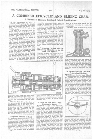
IN • the specification of Felix A. Joseph, of Hong Kong, No. 231,639, a form of gear is described which combines the epicyclic and sliding princi
ples. The sectional view shows the working ports.
The shaft A is connectedwith the engine, whilst the shaft B is coupled to the propeller shaft by means of the flange shown, through which it is free to slide. The casing (C) is free to revolve and carries the two shafts of the planetary wheels.
D is a brake operated by two expanding shoes. E is a cone clutch which, when engaged, brings into operation the direct drive for top gear. The selector lever operates the sliding of the sleeve (F) and the sliding of the shaft (B).
Both the hitter Tarts are fitted with dogs, which can engage the dogs on the faces of the gearwheels which lie on the central shaft. The lever shown at the left-hand end of the box operates the brake and clutch (D and E), whilst the lever at the right-hand end operates the sliding dogs, and by its use any of the lower gears may be selected. A curious pedal action is described, where there are three positions of the pedal—one for neutral, one for engagement of the clutch (E), and one for the engagement of the brake (D).
When in direct drive, the whole of the gears revolve as one solid mass; consequently, any of the dogs can be slid so as to engage any desired wheel preparatory to the release of the clutch and the application of the brake (D). Alentitln is made in the specification of a reverse gear, but no definite description is given as to how the reverse direction drive is obtained.
Perpetual Motion at Last.
IT is curious in these enlightened days, when mechanical knowledge is so common, to see a specification seriously claiming to be for an invention which provides power without the consumption of fuel ! Sidney Renouf, Charles --Lloyd and Austin Green, all of Wales, claim to have discovered a means whereby the pressure from a chamber C48 containing compressed fluid, which is allowed to escape into another chamber which is exhausted, not only provides a motive power sufficient to exhaust and compress a second set of chambers, but will have shme power to spare which would be useful for driving machinery, etc.
In a long and complicated specification they endeavour to describe the apparatus, but we have to admit our inability to follow their meaning. In some countries specifications for perpetual-motion machines are not accepted unless accompanied by a working model. We think it would be well if our Patent Office adopted the same rule.
An" Invention " which will Enable Every Motorist to be his Own Tar Sprayer.
EMILE MOSER and another, in their
specification No. 214,639, seriously suggest that each motorist should carry an apparatus for spraying the roads with tar as they go along ! In a rather poor drawing the3 show a tank of tar which can be fitted to the rear of a pleasure car so thtit it leaves a trail of -tar wherever it goes. What an extraordinary idea A Jack for Use with Large Pneumatic Tyres.
MESSRS. LAKE AND ELLIOT.
Ltd., the well-known makers of motor garage tools, show in their specification No. 231,735 a. jack especially designed for use with motor chars-abanes and vans which are fitted with extra large pneumatic tyres, where a higher lift than usual is needed. The illustration makes it clear that the crutch is pivoted to a hollow screw, which is provided with a keyway and key, which prevent it from revolving. A nut which engages its threads is provided with bevel teeth on its lower face, which engage the upper of the two pinions -shown. When this screw has been brought into operation, and has been wound up to tlr limit of its height, there is a second lifting device in the
form of a solid screw which can be .brought into operation to double the original lift.
The solid screw is operated by means of a second bevel wheel and pinion; as shown. Although we have no doubt that this jack will, like all this firm's productions, be perfectly successful, We are of opinion that we have seen twin screws, one inside the other, in which only one means of operation was employed.
A Torque Rod for Use with Front-wheel Brakes.
WERE it not that the name F.I.A.T. is connected with this specification No. 225,845 we should have thought that the application of a torque rod as shown would have been considered too obvious to be deemed worth while applying for a patent. As shown in the drawing and as described the torque rod is hinged to the frame by means of a shackle, so that it can prevent rotary movement of the front axle duo to the application of the brakes. The shackle may be at the front end or at the rear, as shown. Owing to the shackle, the device can act only as a
torque rod and not as a radius rod; all pressure due to the tendency of the front axle to drag, owing to braking effect, must still be borne by the spring. Although it is claimed that the fitting of this attachment will prevent distortion of the spring when the brake is applied, it is evident that the existence of such a rod interferes with the normal movement of the spring.